Description
ABB PD501-4CH 1SAP260100R3001 Positioning Module
Product Overview
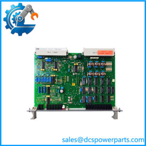
The ABB PD501-4CH 1SAP260100R3001 is a specialized positioning module for ABB AC500 PLC systems. ABB describes the PD501-4CH as a module intended for positioning applications using 24 VDC motors, with four motor axes controlled in forward and reverse directions. Each axis has one analog input for reading position feedback. The hardware therefore combines motor-driving outputs and feedback acquisition in one dedicated module rather than functioning as a conventional analog I/O card.
At the output side, the ABB PD501-4CH 1SAP260100R3001 provides four transistor-based full H-bridge outputs, each rated at 24 VDC and 4 A. This arrangement allows each connected DC motor to be driven in both directions without requiring a separate external reversing stage for the basic motor interface. On the feedback side, four voltage inputs accept 0–10 V position signals, with 12-bit resolution and a specified error of 0.5% at 25°C.
A separate 10 VDC sensor-supply output is provided for position sensors, with 0.1% accuracy and a maximum load current of 90 mA. The module operates from a nominal 24 VDC process supply, and ABB specifies potential isolation at the module level, between analog and digital sections, and between digital output channels in groups of two.
The exact ordering code 1SAP260100R3001 is identified by ABB documentation as PD501-4CH. The suffix matters during procurement because older ABB documentation also lists PD501-4CH under other order-code revisions. Do not substitute an order code solely because the front-panel designation looks identical.
Product Introduction
Four motor axes, four position-feedback inputs, and four reversing power stages are combined in one AC500 positioning module. That makes the a targeted solution for compact DC motor positioning rather than a generic PLC output expansion.
For a legacy AC500 replacement, the critical checks are the exact order code, terminal unit, motor current, feedback range, and PLC hardware configuration. ABB specifies TU541 and TU542 terminal units for this module.
Key Technical Specifications
| Parameter | Value |
|---|---|
| Product Model | |
| Ordering Code | 1SAP260100R3001 |
| Manufacturer | ABB |
| Product Family | S500 / AC500 |
| Product Type | Positioning Module |
| Application | 24 VDC motor positioning |
| Number of Digital Outputs | 4 |
| Output Type | Full H-bridge transistor |
| Output Rating | 24 VDC, 4 A |
| Motor Direction | Forward / reverse |
| Number of Analog Inputs | 4 |
| Feedback Input Type | Voltage |
| Feedback Input Range | 0–10 V |
| Analog Input Resolution | 12 bit |
| Analog Input Error at 25°C | 0.5% |
| Sensor Supply Output | 10 VDC |
| Sensor Supply Accuracy | 0.1% |
| Sensor Supply Maximum Load | 90 mA |
| Process Supply | 24 VDC nominal |
| Output Overload Protection | Yes |
| Module Potential Isolation | Yes |
| Digital Output Isolation | In groups of 2 outputs |
| Analog/Digital Isolation | Yes |
| Recommended Terminal Units | TU541 / TU542 |
ABB’s current catalog documentation identifies the as a four-channel positioning module with four H-bridge outputs and four 0–10 V position-feedback inputs.
Major Features / Practical Advantages
Four-axis DC motor control
The principal function of the is coordinated positioning of four 24 VDC motors. Each motor receives a dedicated H-bridge output, allowing forward and reverse operation from the PLC-controlled module. ABB specifically rates these outputs at 24 VDC and 4 A.
This is considerably different from a standard transistor output module. A conventional digital output may only switch a single direction or drive an external motor-control device. The integrates the reversing power stage directly into the positioning module.
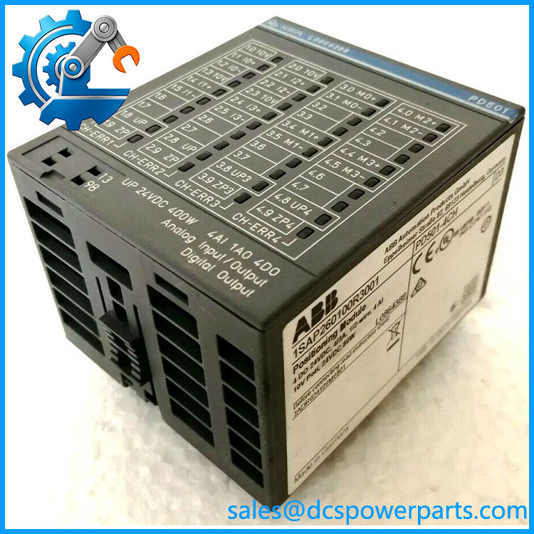
PD501 1SAP260100R3001
Integrated position feedback
Each of the four motor axes has a corresponding 0–10 V analog input for position feedback. The 12-bit conversion provides 4,096 nominal digital levels across the input span. ABB specifies 0.5% error at 25°C, so the converter resolution should not be confused with overall positioning accuracy. Mechanical backlash, sensor linearity, motor characteristics, load inertia, and application logic can all dominate the final positioning result.
24 VDC, 4 A H-bridge outputs
The four transistor H-bridge outputs are rated at 24 VDC and 4 A. This provides a direct interface to appropriately sized DC motors without requiring a separate four-channel reversing contactor arrangement for the basic electrical direction control.
Motor selection still needs care. A 4 A output rating should not be interpreted as permission to connect any motor with a nominal current below 4 A. Starting current, stall current, acceleration profile, duty cycle, thermal conditions, and mechanical load must be considered.
Dedicated 10 V sensor supply
A 10 VDC sensor supply is included for the position-feedback circuitry. ABB specifies 0.1% accuracy and a maximum load current of 90 mA. This can simplify the field wiring for compatible position sensors because an external sensor supply is not necessarily required.
Electrical separation
ABB specifies potential isolation for the module, between the analog and digital channels, and between digital output channels in groups of two. That separation is useful when assessing field wiring and motor-noise paths, although it should not be interpreted as four individually isolated H-bridge outputs.
Output overload protection
The incorporates overload protection for its outputs. This is important for a motor-control module because field faults can occur during commissioning, stalled-motor conditions, wiring errors, or mechanical jams. Protection does not remove the requirement to size the motor and wiring correctly.
Correct terminal unit selection
The ABB catalog associates the with TU541 and TU542 terminal units. These are not incidental accessories; the terminal-unit selection is part of the AC500 I/O installation and should be checked when replacing an older assembly.
Related Products
- TU541 — Screw-terminal unit associated with the positioning module. It provides the field connection interface for the module.
- TU542 — Spring-terminal unit associated with the . The functional module remains the same while the field termination method differs.
- AI531 — AC500 analog input module with broader configurable analog signal capabilities. It is intended for general analog acquisition rather than four-axis motor positioning.
- AX521 — mixed analog I/O module with four analog inputs and four analog outputs. It is a general-purpose analog module rather than an integrated H-bridge positioning device.
- AC522 — analog configurable I/O module with eight analog channels. It provides general analog processing rather than direct four-axis H-bridge motor control.
- CD522 — encoder/PWM module with encoder inputs and PWM outputs. It addresses motion-related applications but uses a different feedback/output architecture.
- DA501 — mixed analog/digital I/O module. Its combination of analog and digital channels makes it a general I/O device rather than a dedicated motor-positioning module.
- DC541-CM — fast I/O and counter module with transistor outputs. It is useful for high-speed discrete functions but does not provide the ‘s four integrated H-bridge stages.
FAQ
Can I use the as a normal four-channel digital output module?
Not as a like-for-like general-purpose replacement. Its four outputs are full H-bridge transistor stages specifically intended for 24 VDC motor positioning. The output architecture and application behavior are different from ordinary single-ended transistor outputs.
What motor voltage does the support?
ABB specifies 24 VDC for the H-bridge outputs, with a 4 A rating per output. The connected motor should be evaluated for starting and stall current as well as its nominal rating.
What position sensor can be connected?
The module provides four voltage inputs with a 0–10 V input range. The sensor must therefore provide a compatible voltage feedback signal. ABB does not describe these four inputs as universal RTD, thermocouple, or current inputs.
Can I hot-swap the ?
Do not assume unrestricted hot-swapping. ABB installation documentation requires installation and maintenance to follow the applicable technical rules and procedures. The module should be isolated and replaced according to the system’s approved maintenance procedure unless the specific system documentation explicitly permits online replacement.
Does the support 4–20 mA position feedback?
No. The documented analog feedback interface is 0–10 V. A 4–20 mA position transmitter would require an appropriate signal-conditioning or conversion arrangement rather than direct connection to the feedback inputs.
Does this support firmware v3.1?
The ordering code 1SAP260100R3001 identifies the hardware as , but it does not establish a specific PLC firmware version. Firmware compatibility should be checked against the installed CPU, engineering software, and project configuration.
What is the difference between 1SAP260100R3001 and 1SAP260100R0001?
Both order codes are associated with the designation in ABB documentation, but they represent different ordering/revision codes. ABB’s older catalog lists 1SAP260100R0001, while later ABB documentation identifies 1SAP260100R3001. For replacement procurement, match the complete order code printed on the installed hardware rather than assuming that every revision is identical.
Does the module include the terminal block?
ABB’s catalog associates the with TU541/TU542 terminal units, so the terminal unit should be confirmed separately when purchasing a replacement. Do not assume a loose automatically includes the required field terminal hardware.
Procurement Note
For an ABB 1SAP260100R3001 replacement, the first check should be the complete order code. ABB documentation identifies this exact code as , while other documentation lists an earlier R0001 ordering code. That is a strong reason to specify the complete part number rather than purchasing simply by the shortened “PD501” designation.
Next, verify the four motor loads. The module’s 24 VDC, 4 A H-bridge rating is only one part of the calculation; motor startup and stall behavior can impose substantially different electrical demands. Confirm the four 0–10 V position sensors and their wiring, then verify whether the installation uses TU541 or TU542.
For surplus or refurbished inventory, request a photograph of the actual 1SAP260100R3001 nameplate and connector area. Check for the exact order code, terminal-unit compatibility, connector damage, enclosure condition, and evidence of previous motor overloads. The official ABB documentation also identifies this product as , so the combination of model designation and complete ordering code should be used for traceability.
One correction is especially important for SEO and technical accuracy: is not a 16-channel analog I/O module and is not an AC 800M S800 I/O module. ABB’s own catalog places it in the /S500 positioning-module family, with four H-bridge motor outputs and four 0–10 V feedback inputs.