Description
Technical Specifications
| Parameter | Specification |
|---|---|
| Product Model | BC810K02 |
| ABB Part Number | 3BSE031155R1 |
| Manufacturer | ABB |
| Product Type | CEX-Bus interconnection unit kit |
| System Compatibility | AC 800M controller family; verify the exact controller and system configuration |
| Nominal Supply Voltage | 24 V DC |
| Supply Voltage Range | 19.2–30 V DC |
| Current Consumption | 50 mA typical; 70 mA maximum at 24 V |
| Power Dissipation | 1.2 W typical |
| Operating Temperature | 0 to +55 °C |
| Storage Temperature | −40 to +70 °C |
| Relative Humidity | 5–95%, non-condensing |
| Protection Rating | IP20 |
| Dimensions | 59 × 185 × 127.5 mm (W × H × D) |
| Package Weight | Approximately 1.5 kg, including base |
| Redundancy | Supported |
| Hot Swap | Supported |
| Mounting | DIN-rail-mounted system assembly; confirm the installation drawing |
Specifications and kit contents are based on ABB’s product selector and datasheet. Confirm the applicable hardware and documentation revision before replacement.
Product Overview
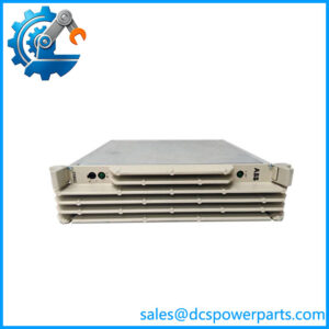
The ABB BC810K02 3BSE031155R1 is a CEX-Bus interconnection unit kit designed for ABB AC 800M controller architectures. Its role is to improve the availability of the communication interface bus by dividing the CEX-Bus into separate segments. The CEX-Bus allows communication interface units to extend the onboard communication capabilities of compatible controllers. Separating the bus into segments helps reduce the impact that a fault in one segment could have on the wider communication arrangement.
The kit is particularly relevant to installations using redundant communication interfaces. ABB identifies support for redundant interfaces, hot swapping, and online CPU replacement as key capabilities. In a fully redundant system with two interlinked BC810 units and a primary/backup CPU pair, the CPU baseplate can be replaced online without disturbing CEX-Bus traffic. That benefit is configuration-dependent: replacing a BC810 unit itself stops traffic to the connected CEX segment, so the two maintenance operations should not be treated as equivalent.
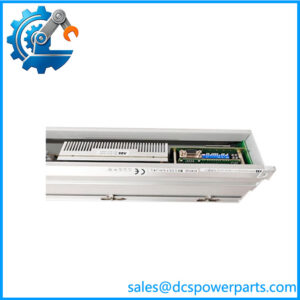
The BC810K02 3BSE031155R1 kit includes two BC810 interconnection units, two TP857 baseplates, a TK851 interconnection cable measuring 1.0 m, and two TB850 CEX-Bus terminators. Procurement teams should confirm that all listed components are included when sourcing a complete kit rather than an individual BC810 unit.
For replacement planning, verify the controller model, existing bus layout, redundancy design, and installed part number. ABB lists compatibility with controller models including PM857, PM861A, PM862, PM863, PM866, PM866A, PM867, and PM891. Compatibility with a listed CPU does not, by itself, confirm suitability for every firmware version or system configuration.
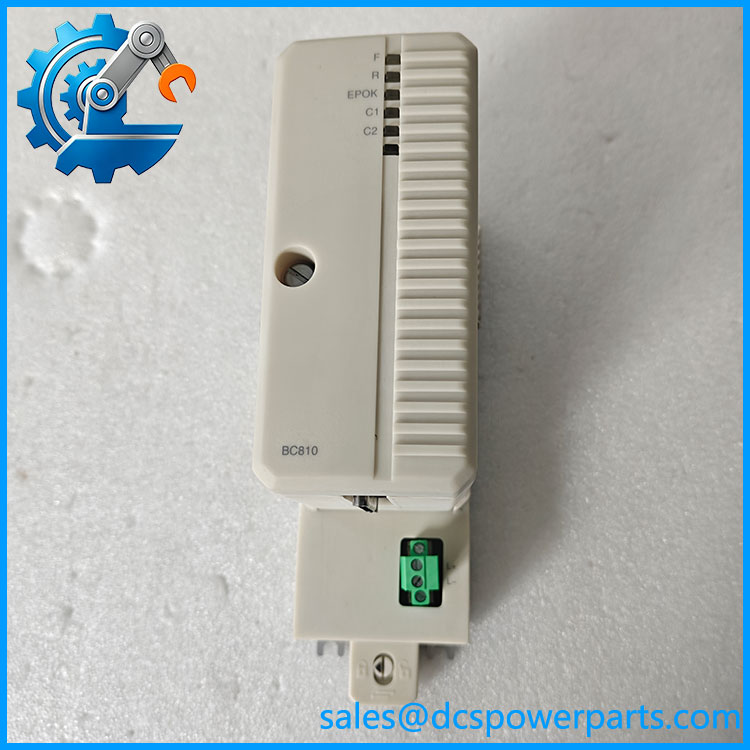
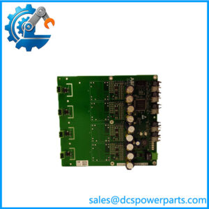
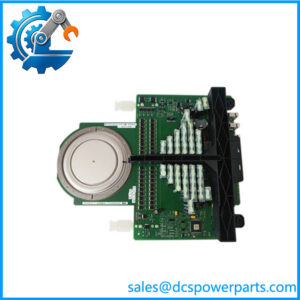
BC810K02 3BSE031155R1
Major Features and Advantages
1. CEX-Bus segmentation
The BC810 divides the CEX-Bus into separate segments, supporting a communication architecture designed for improved availability. This is useful where several communication interface units are installed and the system design needs to limit the impact of a problem affecting one segment.
2. Support for redundant communication interfaces
ABB specifies support for redundant communication interface units. This helps system designers implement communication redundancy where the controller hardware, interface modules, system configuration, and application design support it. The kit does not make an otherwise nonredundant installation fully redundant on its own.
3. Online CPU replacement support
In the specified fully redundant arrangement, the BC810 supports online replacement of the CPU baseplate without disturbing CEX-Bus traffic. This can help maintenance teams plan controller service without unnecessarily interrupting communications. The benefit depends on the complete redundant arrangement being correctly installed and operational.
4. External power supply
The unit uses an external 24 V DC supply, with a documented operating range of 19.2–30 V DC. The power supply and logic board contain the converter and bus-interconnection logic, while the baseplate provides the CEX-Bus and external power connections.
5. Hot-swap support
ABB lists hot swapping as a supported capability. This should be interpreted according to the system’s approved maintenance procedure; it does not mean every component in the kit can be removed without interrupting communications. In particular, ABB states that replacing the unit stops traffic to its connected CEX segment.
6. Defined kit contents
The kit combines the interconnection units, baseplates, cable, and terminators required by the specified assembly. Checking the contents against the original bill of materials helps prevent delays caused by missing connection or termination components.
Applications
The ABB BC810K02 3BSE031155R1 is intended for compatible ABB AC 800M control-system installations where CEX-Bus segmentation and communication-interface redundancy are part of the system design.
Typical maintenance and engineering scenarios include:
- DCS communication infrastructure: Interconnecting CEX-Bus segments within a supported AC 800M controller arrangement.
- Redundant controller installations: Supporting architectures with redundant communication interfaces and primary/backup CPUs.
- Planned controller maintenance: Replacing a CPU baseplate under the applicable online maintenance procedure, where the documented redundant configuration is in place.
- Legacy system repair: Replacing an installed BC810K02 kit when the original equipment documentation specifies the same part number.
- Spare-parts planning: Stocking a complete kit for installations where the supplied interconnection units, baseplates, cable, and terminators are all required.
Before selecting the kit, engineers should check the controller model, the number and type of communication interface units, the CEX-Bus topology, and the existing redundancy arrangement. The installed hardware and system documentation should determine whether a complete kit or an individual component is needed.
This kit should not be treated as a general-purpose network switch or as a substitute for other ABB interconnection products solely because they serve related communication-system functions. For example, ABB lists the BC820K02 as a separate product with its own article number, 3BSE071500R1. Its suitability as an alternative must be assessed against the required system architecture and product documentation.
Related Products
| Model / Part Number | Relationship |
|---|---|
| Individual CEX-Bus interconnection unit supplied as part of the BC810K02 kit. | |
| TP857 | Baseplate included in the kit; two units are specified. |
| TK851 | 1.0 m interconnection cable included in the kit. |
| TB850 | CEX-Bus terminator included in the kit; two units are specified. |
| BC820K02 — 3BSE071500R1 | Separate ABB CEX-Bus-related product; verify functional and configuration compatibility before considering it as an alternative. |
| PM857 | Compatible controller model listed by ABB. |
| PM861A | Compatible controller model listed by ABB. |
| PM862 | Compatible controller model listed by ABB. |
| PM866A | Compatible controller model listed by ABB. |
| PM891 | Compatible controller model listed by ABB. |
The listed relationships are based on ABB product documentation. They do not imply that every item is interchangeable with the complete 3BSE031155R1 kit.
Installation and Maintenance
Before installing the ABB 3BSE031155R1, confirm the controller type, existing CEX-Bus arrangement, redundancy design, and kit contents against the approved engineering documentation. Check that the two units, two TP857 baseplates, TK851 cable, and two TB850 terminators are present if the purchase is intended to replace the complete kit.
Verify the 24 V DC supply and ensure that it remains within the specified 19.2–30 V DC range. Check that the cabinet environment is within the documented operating temperature of 0 to +55 °C and relative humidity of 5–95%, non-condensing. The IP20 rating is intended for protected installation environments, not exposure to water or conductive dust.
Follow the plant’s isolation, authorization, and maintenance procedures before working on the equipment. Do not assume that hot-swap support permits removal of any component under all operating conditions. In particular, ABB states that replacing the interconnection unit stops traffic to the connected CEX segment. The online CPU-baseplate replacement capability applies to the specified fully redundant configuration and must be handled according to the relevant procedure.
After installation, inspect the bus connections and termination arrangement, verify the external supply, and check controller and communication-interface diagnostics. Confirm that the intended redundancy configuration is recognized and that the expected CEX-Bus segments are operating before returning the system to normal service.
Product Assurance
When sourcing the ABB 3BSE031155R1, verify the full model and part number against the installed hardware and the system bill of materials. Because the kit contains several separate components, confirm whether the quoted item is a complete kit or an individual unit.
A responsible supplier should disclose the actual item condition—new, unused surplus, refurbished, or used—and provide photographs of the supplied hardware and labels when possible. Any testing statement should identify what was tested and what remains unverified. A visual inspection alone does not establish full functional performance or compatibility with a particular controller configuration.
For replacement projects, confirm that the required accessories are included and that the proposed item matches the existing CEX-Bus topology. Record any differences in revision markings, packaging, or kit contents before installation.
The manufacturer documentation establishes the kit’s primary function, specified contents, electrical ratings, and supported capabilities. Final suitability should still be checked against the installed controller and approved system configuration before the component is put into service.