Description
Product Overview
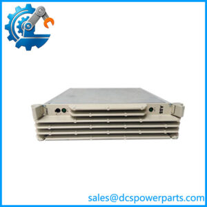
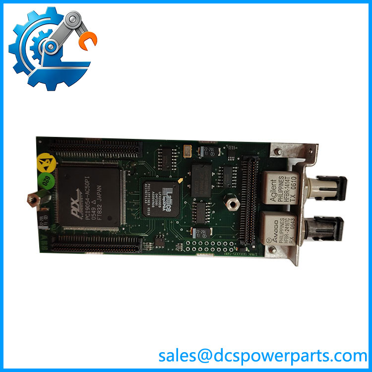
1MRK002122-AB is the short-range optical line data communication module of ABB’s Relion 670 series, the board the product guides list as “Optical short range LDCM” and the factory labels 670LDCM02 SHORT. It is not a general-purpose communication card: it is the physical layer that carries sampled current values, time reference, trip and block signals and eight spare binary signals between two ends of a protected line, framed according to IEEE C37.94 and clocked synchronously at 64 kbit/s in its default mode.
Placement matters as much as function. The module occupies one of the remote-communication positions inside a RED670, REG670, REL670, RET670 or REC670 chassis, and a single IED can hold up to four of them, which is exactly what a three-ended line or a redundant channel arrangement requires. Each fitted 1MRK002122-AB represents one duplex fiber pair to one remote end, so channel count and topology are the same engineering decision.
The design constraint that decides whether a scheme works is optical budget, not card count. With 62.5/125 µm graded-index fiber the module offers 13 dB of budget and roughly 3 km of reach; on 50/125 µm it delivers 9 dB and about 2 km. Minimum output is −17 dBm against a receiver sensitivity of −30 dBm, and a selectable high-power setting adds headroom where the route runs close to the limit. That margin is what absorbs splice loss, connector ageing and the 20–30 year service life the application guide assumes.
Technical Specifications
表格
| Parameter | Value |
|---|---|
| Model | 1MRK002122-AB (revision r00) |
| Manufacturer | ABB (Sweden) |
| Product type | Line data communication module (LDCM), optical short range, IED plug-in board |
| Optical connector | ST, duplex (TX/RX pair) |
| Fiber type | Graded-index multimode 62.5/125 µm; 50/125 µm supported with reduced budget |
| Wavelength | 820 nm peak emission, 865 nm nominal, 792 nm minimum |
| Optical budget | 13 dB on 62.5/125 µm, 9 dB on 50/125 µm |
| Typical reach | About 3 km on 62.5/125 µm, about 2 km on 50/125 µm, subject to budget calculation |
| Output and sensitivity | −17 dBm minimum launch power (62.5/125 µm), −30 dBm receiver sensitivity |
| Protocol and framing | IEEE C37.94, synchronous, HDLC framing |
| Data rate | 64 kbit/s default; 2 Mbit/s mode selectable |
| Channel capacity per IED | Up to four remote communication interfaces |
| Payload per 64 kbit/s channel | Three-phase current samples every 5 ms, time information, trip/block/alarm, eight binary signals |
| Supply | Fed from the IED backplane; no external power connection |
| Slot positions | Communication module positions P30:5, P30:6, P31:3, P32:2, P32:3, depending on chassis |
| Standards | IEC 60255-26 for EMC, IEC 60255-1 and IEC 60255-27 for the parent IED |

- 1MRK002122-ABr00
Key Features and Advantages
One duplex pair carries the whole protection conversation
A 64 kbit/s channel from 1MRK002122-AB moves three-phase current samples every 5 ms together with the time reference that keeps the two ends aligned, plus trip, block and alarm flags and eight binary signals available for any purpose — transfer trip from external protection, interlocking, or status exchange. One fiber pair therefore replaces a separate teleprotection channel, which simplifies both the scheme and the cable schedule.
Optical budget as a design input, not an afterthought
The 13 dB budget on 62.5/125 µm is stated together with the attenuation assumptions used to derive it: 3 dB/km in fiber, 1.5 dB per ST connector, 0.5 dB per repair splice and a 0.1 dB/km aging allowance. A route survey that uses those same numbers predicts reach before any hardware is ordered, and the high-power setting provides roughly 3 dB of extra margin for routes that sit near the limit.
Topologies beyond a simple two-ended line
Up to four modules can sit in one chassis, so a three-ended line can terminate two channels per end while a redundant arrangement runs a main and a standby channel that the signal matrix switches over automatically. On breaker-and-a-half or ring-bus arrangements where two current transformer sets feed one end, two channels — or a single summed channel in software — cover the dual-CT case.
2 Mbit/s mode for link forwarding
Where a station sits mid-route or a mesh of lines shares endpoints, the 2 Mbit/s mode lets 1MRK002122-AB forward both local and received remote currents onward, so a chain of IEDs behaves as one differential zone rather than a set of isolated pairs. The mode is a setting, not a different board, which keeps spares planning simple.
Applications
The primary use is line differential protection on HV and EHV transmission lines where both ends sit within a few kilometers of each other in fiber terms — a 400 kV and 110 kV substation sharing a compound, a generator step-up plant tied to a nearby switchyard, or two bays of the same station protecting a short tie. In these layouts the short-range budget is sufficient and the cost of single-mode optics is avoided entirely.
Urban distribution networks use 1MRK002122-AB across cable circuits between adjacent substations, where the physical route is short but the protection requirement is identical to a long overhead line. Industrial captive grids — mine feeder lines, steel plant interties, refinery internal transmission — pair the module with RED670 terminals to obtain unit protection across a private network without leasing a telecom channel.
Binary signal transfer is the second application family: teleprotection transfer trip between two stations, interlocking between busbar and line protection, or status exchange for a black-start sequence. Because the eight binary signals travel in the same telegram as the currents, they inherit the same supervision and the same fiber route.
Bench and factory testing forms the third: back-to-back testing of two IEDs through a short multimode patch cord is standard practice at commissioning, and 1MRK002122-AB pairs directly without any intervening converter.
Related Products
1MRK002311-AA — medium range LDCM, single-mode 9/125 µm at 1310 nm with FC/PC connector, 22 dB budget for routes up to roughly 60–80 km; the direct step up in reach. 1MRK002311-BA — long range LDCM, single-mode at 1550 nm, 26 dB budget for distances in the 110–130 km class. 1MRK005500-AA — Ethernet SFP module, optical LC connector, for the station bus rather than the protection channel. 1MRK005500-BA — Ethernet SFP module, RJ45 connector, the copper variant of the same station-bus option. 1MRK002266-EA — optical Ethernet module (OEM) for IEC 61850 station communication. 1MRK001608-AB / 1MRK001608-BB / 1MRK001608-CB — serial SPA/LON/DNP/IEC 60870-5-103 modules in plastic, plastic-glass and glass versions, the alternative when the remote end is reached over serial telecontrol rather than fiber. 1MRK002309-AA — galvanic RS485 communication module for short-distance copper links. 1MRK007002-AA — GPS time module, used where differential protection relies on a global clock reference instead of derived channel timing. 1MRK002282-AB — IRIG-B time synchronization module, the alternative time base for the same schemes. RED670 / REG670 / REL670 — parent IEDs in which 1MRK002122-AB is installed.
Installation and Maintenance
Before installation: confirm the chassis has a free remote-communication position — the slot map differs between 1/2 and 3/4 cases, and modules are placed at P30:5, P30:6, P31:3, P32:2 or P32:3 accordingly. Count the channels the scheme needs before ordering fiber, since a three-ended line wants two modules per end. Measure the route with an optical time-domain reflectometer and compare the result against the 13 dB budget, then decide low or high power setting: low for routes up to about 1 km, high beyond that. Only then de-energize the IED and fit 1MRK002122-AB.
Maintenance practice: clean every ST ferrule before mating and after any intervention on the patch panel, because a single contaminated connector can consume more budget than the entire aging allowance. Record launch power and received level at commissioning, then re-measure annually — a 2–3 dB drift points to connector degradation long before the channel raises an alarm. One end must be configured as clock master and the other as slave; a mismatch shows up as intermittent channel failure under load, not as an obvious fault. After any fiber work, run a loop-back test and confirm the channel supervision counters before restoring the protection to service.
Warranty and Supply
1MRK002122-AB is supplied as a plug-in module with revision level matched to the ordering position, and each unit is verified on a fiber loop-back bench: launch power, received level, C37.94 framing and channel status are all recorded before dispatch so the commissioning engineer starts from known values. A 12-month warranty applies under standard industrial-automation practice. Where a chassis carries several modules, revision consistency across positions is checked at packing, because mixed revisions in one IED complicate later diagnosis. Technical support covers slot assignment, master/slave clock configuration, optical budget review and the choice between low and high power settings.