Description
Technical Specifications
| Parameter | Specification |
|---|---|
| Model | ADV151-P00 |
| Manufacturer | Yokogawa |
| Product type | Isolated digital input module |
| Number of input channels | 32 |
| Rated input voltage | 24 V DC, sink/source |
| Input ON voltage | 18–26.4 V DC |
| Input OFF voltage | 5.0 V DC or less |
| Input current | 4.1 mA ±20% per channel at rated voltage |
| Maximum allowable input voltage | 30 V DC |
| Input-to-system withstand voltage | 2 kV AC for 1 minute |
| Common-to-common withstand voltage | 500 V AC for 1 minute, common shared every 16 channels |
| Status-input response time | 8 ms or less |
| Minimum ON detection time for pushbutton input | 20 ms |
| Maximum pushbutton ON/OFF cycle | 25 Hz |
| Maximum current consumption | 500 mA at 5 V DC |
| Approximate weight | 0.3 kg |
| Connection options | Pressure-clamp terminal, dedicated cable, or MIL connector cable, subject to configuration |
| Product condition | Confirm for the individual unit |
These specifications are published for the ADV151 module family. The exact suffix indicates the pushbutton-input and basic-type configuration; connection accessories are selected separately where required.
Product Overview
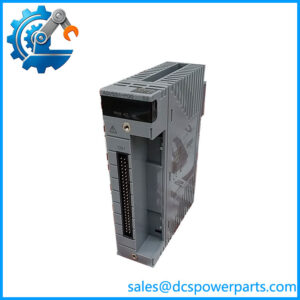
The Yokogawa ADV151-P00 is a 32-channel isolated digital input module designed for industrial control systems that use 24 V DC field signals. It receives discrete ON/OFF states from field devices and makes those states available to the control system for logic execution, interlocking, alarm processing, and equipment-status monitoring. Typical signal sources include auxiliary contacts, limit switches, pushbuttons, and compatible discrete sensors.
The ADV151 family is documented for use with Yokogawa FIO hardware in supported field control units and ESB bus node units. Its 32-channel design allows multiple discrete signals to be collected in one module, helping consolidate wiring and I/O allocation within a control cabinet. The module supports sink/source input arrangements, but the actual wiring must follow the field-device circuit design and the applicable Yokogawa connection diagram.
The ADV151-P00 suffix identifies a pushbutton-input version in the basic configuration. In addition to ordinary ON/OFF status detection, the pushbutton function can count input edges within the specified operating limits. This is useful for selected operator controls and discrete event signals, but it should not be confused with the separate SOE-capture variant. The module’s response time and pushbutton detection limits also mean that it should not be selected for high-speed event capture without checking the full system requirements.
When purchasing a replacement, verify the full model code, the terminal or cable interface, and the host-node compatibility. The module is not interchangeable with a digital output card or with input modules designed for different signal voltages. Correct wiring, channel configuration, and system engineering are essential to reliable operation.
Major Features and Advantages
32-channel digital input acquisition
The ADV151-P00 receives 32 discrete field signals at a rated input voltage of 24 V DC. A 32-channel module can reduce the number of separate I/O cards needed for cabinets containing numerous equipment-status contacts. Its maximum allowable input voltage is specified as 30 V DC, so field circuits must remain within the documented limits.
Isolated input architecture
The is specified as an isolated digital input module. Published specifications give a 2 kV AC withstand rating between input signal and system, and 500 V AC between commons for one minute, with a common shared every 16 channels. These ratings apply under the manufacturer’s stated test conditions; they are not permission to apply test voltages during normal operation or to ignore the field wiring’s insulation requirements.
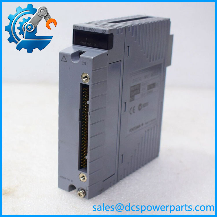
ADV151-P00
Pushbutton-edge counting
The -P function supports pushbutton input and counting of pushbutton edges. The published specifications list a minimum ON detection time of 20 ms and a maximum ON/OFF cycle of 25 Hz for this function. These limits should be considered when using the module for operator commands or pulse-like discrete signals. Applications requiring faster counting or precise time stamping should be evaluated against a module designed for that purpose.
Defined ON/OFF thresholds
The module specifies an ON voltage of 18–26.4 V DC and an OFF voltage of 5 V DC or less. The region between those ranges should not be treated as a guaranteed logic state. Field circuits should be designed to provide sufficient voltage margin at the module terminals, taking cable drops and device leakage into account. This is particularly important when several devices share a supply or when long cable runs are involved.
Multiple connection options
Yokogawa documentation identifies pressure-clamp terminals, dedicated cables, and MIL connector cables for the family, subject to the applicable hardware configuration. This flexibility supports different cabinet wiring arrangements. It does not mean every connection accessory is included with every module; verify the terminal block or cable part number when ordering.
Integration with Yokogawa FIO systems
The family is intended for compatible Yokogawa FIO installations, including supported field control units and ESB bus node units. Its suitability depends on the host hardware, slot assignment, system configuration, and the required redundancy arrangement. Check the installed system documentation before substituting a different variant.
Applications
Equipment status monitoring
The -P00 can acquire discrete feedback signals from pumps, fans, valves, motor starters, and other equipment where 24 V DC ON/OFF indications are used. The control system can use these signals to show equipment status, verify command feedback, and trigger alarms when the observed state differs from the expected state.
Operator pushbuttons and local controls
The pushbutton-input function can support selected operator commands and contact-edge counting within the specified limits. Typical examples include local acknowledge buttons or discrete operator actions where the control logic needs to detect a change of state. The exact application must account for contact bounce, minimum detection time, and the module’s maximum supported ON/OFF cycle.
Process interlocks and permissive logic
Discrete inputs are often used to confirm that equipment is in a safe or permitted state before a control sequence proceeds. Examples include door-closed contacts, auxiliary contacts from motor starters, and limit-switch feedback from actuated valves. The -P00 can provide these signals to a compatible Yokogawa control system, but any safety-related function must use hardware and architectures approved for the required safety integrity level. A standard digital input module should not be assumed to be a safety-rated input.
Plant utilities and distributed I/O cabinets
Water treatment systems, power utilities, chemical processes, and manufacturing facilities commonly use discrete signals to monitor local equipment. A 32-channel input module can consolidate these signals at a supported remote I/O location, reducing the need to route every field signal back to the main control room. The actual benefit depends on cabinet layout, wiring distance, and the design of the control network.
Maintenance and fault replacement
When a discrete input fails to change state, the cause may be a faulty field contact, an incorrect supply, an open circuit, a loose terminal, or an input-module fault. Checking the voltage at the module terminal and comparing it with the published ON/OFF thresholds helps isolate the issue. A replacement module should be installed only after confirming the correct input type and terminal arrangement.
Related Products
These Yokogawa modules belong to the same general digital I/O family or control-system environment, but their functions and electrical characteristics differ.
| Model | Relationsh |
|---|---|
| -E | Related digital input variant with SOE capture; confirm the complete suffix before selection. |
| ADV157 | 32-channel, 24 V DC isolated digital input module with pressure-clamp terminal support. |
| ADV161 | 64-channel, 24 V DC isolated digital input module with different input-current characteristics. |
| ADV551 | 32-channel isolated digital output module for 24 V DC applications; not an input-module substitute. |
| ADV561 | 64-channel isolated digital output module. |
| ADV141 | 16-channel isolated digital input module for 100–120 V AC signals. |
| ADV142 | 16-channel isolated digital input module for 220–240 V AC signals. |
| ATB5S-00 | Pressure-clamp terminal block for compatible digital input installations. |
| ATB5D-00 | Dual pressure-clamp terminal block for supported configurations. |
| ACCC01 | Connector cover accessory for the applicable MIL-cable arrangement. |
The model family and connection options are described in Yokogawa’s digital I/O documentation. Verify the complete ordering code and required accessories before considering any related item as a replacement.
Installation and Maintenance
Before installin, confirm that the host field control unit or ESB bus node supports the module and that the field circuits are designed for 24 V DC discrete inputs. Check the full model suffix and identify the required terminal block or cable. Isolate the relevant circuits in accordance with site safety procedures before removing or inserting the module.
For each channel, verify the field device’s output type, polarity, and expected voltage. At the module terminal, the specified ON range is 18–26.4 V DC and the OFF threshold is 5 V DC or less. If the measured voltage falls between these ranges, investigate the field circuit rather than assuming that the module should report a stable state. Check for supply sag, poor connections, leakage current, and incorrect common wiring.
During troubleshooting, compare the physical input voltage with the channel status reported by the control system. Inspect terminals and connectors for looseness, corrosion, contamination, or damage. For pushbutton applications, check that the signal timing is compatible with the minimum ON detection time and maximum supported cycle. If the fault persists, test the circuit with an approved test source and follow the site’s procedure for confirming a module fault.
After replacement, verify all affected channels using known field states or an approved test setup. Confirm that input status, interlocks, alarms, and control logic behave as expected before returning the equipment to operations. Record the replacement model, channel checks, and any unresolved faults in the maintenance log.
Product Assurance
For procureme, confirm the full model code and the required system configuration before shipment. Published specifications establish the family’s 32-channel, 24 V DC isolated-input function and its pushbutton-input capability, but they do not establish the condition or test history of an individual unit.
Recommended incoming checks include:
- Part-number verification: to the purchase order and approved spare-parts list.
- Physical inspection: Check the housing, connector, contacts, and label for damage or alteration.
- Electrical compatibility: Confirm the 24 V DC input type and verify that the field circuits remain within the specified limits.
- Accessory verification: Confirm the terminal block, dedicated cable, or MIL connector arrangement required by the installation.
- Functional testing: Request evidence of channel-level input testing and, where applicable, pushbutton-function testing.
- Condition disclosure: Obtain written confirmation of whether the supplied unit is new, used, or refurbished, together with applicable warranty terms.
For control-system maintenance, a matching model number is only one part of acceptance. Confirm the hardware compatibility, documented condition, and test evidence before placing the module into service.