Description
Key Technical Specifications
The VMER-64 designation is not sufficiently unique to establish a reliable manufacturer-specific datasheet. I would therefore avoid inventing electrical, mechanical, or environmental specifications.
| Parameter | Identification |
|---|---|
| Model | VMER-64 |
| Product Type | VMEbus rack / backplane system |
| Bus Standard | VMEbus / VME64 |
| Slot Capacity | 64 slots, based on the model designation |
| Board Format | Typically 6U VME architecture |
| Application | Industrial / embedded VME systems |
| CPU Support | VME CPU boards, depending on backplane configuration |
| I/O Support | VMEbus I/O and interface boards |
| Power Supply | System-specific; verify chassis configuration |
| Backplane | VMEbus backplane |
| Manufacturer | Not reliably established from model number alone |
| Exact Dimensions | Verify OEM documentation |
| Operating Temperature | Verify OEM documentation |
| Input Voltage | Verify chassis power-supply label |
| Connector Configuration | Verify backplane revision |
Important: I would not treat “VMER-64” as a confirmed 64-slot chassis without checking the physical unit. The suffix strongly suggests a 64-slot VME configuration, but the model number alone is not enough to establish the exact backplane topology, power architecture, or manufacturer.
Product Introduction
VMER-64
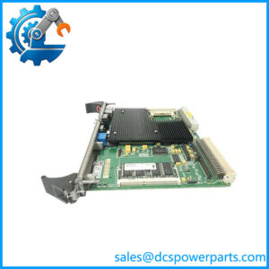
The VMER-64 appears to be a high-density VMEbus rack/backplane assembly intended to accommodate multiple VME boards. In a legacy automation or embedded-computing system, such a rack can host CPU, memory, digital I/O, analog I/O, communications, and interface cards on a common VMEbus.
The critical engineering issue is the exact backplane implementation. VME systems can differ substantially in P1/P2/P0 connectivity, VME64 support, rear I/O, power distribution, slot count, and system-controller requirements. Those details must be verified from the chassis documentation before replacement.
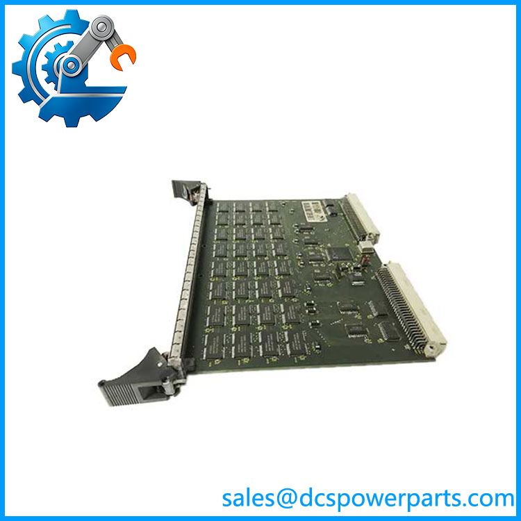
VMER-64
Application Scenarios & Field Pitfalls
Engineering Pain Point
With old VME systems, the rack itself is often overlooked. Engineers see a failed CPU or I/O board and start swapping cards, when the real problem is a degraded backplane connector, missing supply rail, damaged bus line, or intermittent slot. A high-density VMER-64 installation makes this more likely because many boards share the same backplane infrastructure.
Typical Applications
- Industrial Automation — Legacy VME-based PLC, motion-control, and machine-control systems.
- Power Generation — Embedded control and data-acquisition equipment in older turbine and plant systems.
- Test & Measurement — Multi-board acquisition, signal-conditioning, and instrumentation platforms.
- Defense/Aerospace Test Equipment — High-density VME computing and I/O assemblies.
Technical Pitfalls to Avoid
- Confirm the manufacturer first.
is not sufficiently distinctive to establish an OEM with confidence. Check the chassis label, backplane PCB marking, and manufacturer logo. - Do not assume all 64-slot VME backplanes are equivalent.
Check whether the system uses VME32, VME64, VME64x, or another implementation. The backplane wiring and connector population can differ. - Inspect P1 and P2 carefully.
VMEbus connectors are subject to mechanical wear after repeated board replacement. Bent contacts and oxidized connections can create intermittent bus faults. - Check the system controller position.
VME systems normally have a designated system-controller slot. Moving boards without understanding the slot architecture can cause bus arbitration or interrupt problems. - Verify rear I/O.
Some VME racks route field signals through transition modules or rear connectors. Others use front-panel I/O. Do not replace a chassis without checking the existing cabling architecture. - Measure power at the backplane.
Do not assume that the chassis power supply is healthy because fans are running. Check the actual VME supply rails under load. - Check for slot-specific faults.
If only one position repeatedly fails while other boards operate normally, inspect the corresponding backplane slot before replacing the board. - Do not mix VME generations blindly.
VME64 and VME64x hardware introduced additional features and connector arrangements. A physically compatible board is not necessarily electrically equivalent in every chassis. - Document the rack before disassembly.
Photograph every board position, slot number, transition module, and cable. On a legacy system, that record can be more valuable than the original equipment label. - Verify airflow.
A 64-slot rack can have substantial heat density. Confirm fan operation and airflow direction before returning the system to service.
Related Products
- VMEbus 6U CPU Boards — These provide the processor function within a VME rack. They are the primary computing elements and depend on the backplane for bus communication.
- VME64 CPU Modules — Higher-performance VME processors using VME64 extensions. Verify backplane and power compatibility before installing them into an older VME chassis.
- VME Digital I/O Modules — Provide discrete input/output functions for legacy industrial-control applications. These are installed into the rack rather than being part of the chassis itself.
- VME Analog I/O Modules — Used for analog acquisition and output. Their actual signal range and isolation depend on the individual module.
- VME Communication Modules — Provide serial, Ethernet, CAN, fieldbus, or other communications within the VME system. These are common additions to legacy automation racks.
- IndustryPack Carrier Boards — VME carrier boards such as the TEWS TVME200 family allow IndustryPack modules to operate within a VME chassis. This is useful when modernizing individual I/O functions without replacing the entire VME platform.
- VME Transition Modules — Used where field wiring or rear I/O must be brought out through the back of the VME rack. Exact compatibility depends on the carrier and backplane.
- VME Power Supplies — Supply the required VME backplane rails. A replacement must be selected according to the actual rack’s current requirements rather than slot count alone.
- VME64x Backplanes — Later-generation VME backplanes with additional connector/power capabilities. They should not automatically be substituted for a conventional VME backplane.