Description
Key Technical Specifications
The designation VME-PMC-CADDY is used generically enough that I cannot responsibly assign a manufacturer-specific datasheet to it from the model number alone. The following describes the functional architecture rather than unverified OEM-specific electrical ratings.
| Parameter | Specification |
|---|---|
| Model | VME-PMC-CADDY |
| Product Type | VMEbus PMC Carrier |
| Host Bus | VMEbus |
| Mezzanine Interface | PMC |
| PMC Standard | PCI Mezzanine Card |
| Typical Board Format | 6U VME |
| PMC Slots | Typically 1; verify actual board |
| PMC Electrical Interface | PCI-based PMC interface |
| Application | VME system expansion |
| Typical Functions | I/O, communications, storage, data acquisition |
| Front/Rear I/O | Manufacturer/configuration dependent |
| VME Addressing | Manufacturer dependent |
| VME Data Width | Manufacturer dependent |
| DMA Support | Verify OEM implementation |
| Operating Temperature | Verify OEM datasheet |
| Power Input | VME backplane; exact rails/current depend on carrier |
| Manufacturer | Not established from model number alone |
Do not use the above as a substitute for the original hardware manual. In particular, PMC slot count, VME data width, rear-I/O support, address mapping, interrupt routing, and DMA behavior vary significantly among VME PMC carrier designs.
Product Introduction
VME-PMC-CADDY
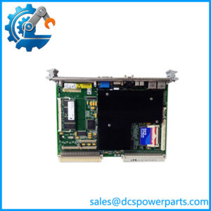
The VME-PMC-CADDY is a VMEbus carrier concept designed to allow a PMC (PCI Mezzanine Card) to operate inside a VME-based embedded system. This approach lets a legacy VME platform use newer PMC-based functions such as Ethernet, serial communication, data acquisition, storage, or specialized digital I/O without replacing the complete chassis.
The carrier itself normally provides the electrical and mechanical bridge between the PMC and VMEbus. The actual application function comes from the installed PMC. That distinction matters when troubleshooting or specifying a replacement.
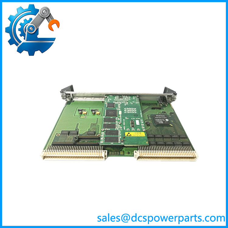
VME-PMC-CADDY
Application Scenarios & Field Pitfalls
Engineering Pain Point
A PMC carrier can make an old VME system look deceptively simple: one carrier, one mezzanine card, one VME slot. In practice, the carrier determines how the PMC’s PCI resources are exposed to the VME system. If address mapping, interrupts, rear I/O, or power requirements differ from the original carrier, a physically compatible PMC may still fail to initialize.
Typical Applications
- Industrial Automation — Adding Ethernet, serial, motion, or specialized I/O to legacy VME controllers.
- Test & Measurement — Hosting PMC data-acquisition and signal-processing cards in VME instrumentation.
- Embedded Control — Integrating PCI-based mezzanine functions into established VME architectures.
- Aerospace / Defense Test Systems — Maintaining legacy VME platforms while adding PMC-based communication and acquisition hardware.
Technical Pitfalls to Avoid
- Identify the carrier manufacturer before replacement.
“VME-PMC-CADDY” is not enough to establish the exact electrical implementation. Check the PCB artwork, manufacturer logo, and revision. - Do not confuse PMC with PCI Express PMC variants.
Conventional PMC uses a PCI electrical architecture. Newer mezzanine standards can look similar but are not automatically compatible. - Check VME slot requirements.
A 6U carrier may use P1/P2 and, depending on implementation, additional connectors or rear-I/O paths. Verify the actual backplane before installation. - Check interrupt routing.
PMC PCI interrupts must be mapped into the host VME system. A carrier with different interrupt routing can prevent otherwise healthy PMC hardware from being recognized correctly. - Verify address mapping.
The carrier determines how PMC PCI resources appear to the VME host. Software drivers may depend on the original carrier’s resource mapping. - Check DMA support.
Some VME-PMC carriers support DMA or advanced VME transfer modes; others do not. Do not assume high-speed data transfer capability from the PMC itself. - Inspect the PMC mounting hardware.
Standoffs and mounting screws are part of the mechanical interface. A poorly secured PMC can cause intermittent connector faults under vibration. - Verify rear I/O requirements.
If the PMC uses rear I/O, the carrier and VME backplane must provide the required signal path. A front-I/O carrier may not be an acceptable replacement. - Check power consumption.
A high-performance PMC can draw substantially more power than a simple communications card. Verify the carrier and VME power budget. - Preserve the original software configuration.
Legacy VME systems may contain driver-level assumptions about PCI resource allocation, interrupt vectors, or board identification. A carrier replacement can therefore require software validation even when the PMC itself is unchanged.
Related Products
- VME64 PMC Carrier Boards — Later-generation VME carriers supporting PMC devices with VME64 features. Useful for system upgrades, but backplane compatibility must be checked.
- 6U VME PMC Carrier Modules — Common architecture for integrating one or more PMC devices into a 6U VME chassis. Exact connector and rear-I/O arrangements vary by manufacturer.
- TEWS TVME200 Series — VMEbus carrier family for IndustryPack modules. Functionally similar as a mezzanine-carrier concept, but IndustryPack is not PMC and the modules are not interchangeable.
- VMEbus CPU Boards — Provide the host processor and VMEbus master functionality. The VME-PMC-CADDY normally depends on a host CPU/system controller rather than replacing it.
- PMC Ethernet Modules — Add Ethernet connectivity to VME systems through the PMC interface. The specific driver and VME carrier support must be checked.
- PMC Serial Communication Modules — Provide RS-232/422/485 or other serial interfaces while using the VME carrier as the host interface.
- PMC Digital I/O Modules — Add discrete I/O to legacy VME systems. These are application modules installed on the carrier rather than substitutes for the carrier.
- PMC Data Acquisition Modules — Provide analog acquisition and high-speed measurement capability. Their electrical interface remains PMC/PCI even though the host system is VME.
- VME Transition Modules — Provide rear-panel I/O for VME systems where the PMC carrier routes signals through the backplane. These are particularly important when the original installation uses rear field wiring.