Description
SST 5136-DN-VME DeviceNet VME Interface Card
Product Overview
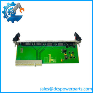
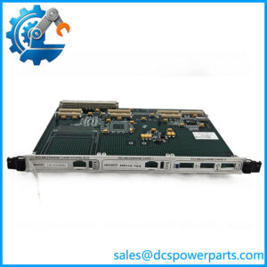
The SST 5136-DN-VME is a 6U VMEbus interface card designed to connect a VME-based control computer or industrial controller to DeviceNet and other CAN-based networks. Unlike a passive VME communication adapter, the SST 5136-DN-VME contains its own 16 MHz V40 microprocessor and 128 KB of RAM. Its architecture uses downloadable application modules, allowing the host VME system to load the software required for the intended network function. An optional EPROM can also be installed for systems where application loading from the VME host is impractical.
From a system-integration perspective, the SST 5136-DN-VME sits between the VMEbus backplane and the field-level DeviceNet/CAN network. The card provides an optically isolated CAN interface, a standard 5-pin DeviceNet connector, selectable VME control-register addressing, configurable VME interrupt levels, and 128 KB of shared RAM accessible by the host application. DeviceNet operation supports the standard 125, 250, and 500 Kbaud rates, while the CAN interface can operate up to 1 Mbaud.
That distinction matters when replacing a failed card. A physically compatible VME board is not necessarily a functional replacement if the existing system depends on a particular SST application module, EPROM image, VME address configuration, interrupt level, or host-side software interface. The hardware reference specifically treats the application module as a separate element of the system. For a legacy VME control platform, retaining the correct software image and host configuration can be just as important as matching the board part number.
Product Introduction
Legacy VME systems often fail at the communication layer long before the host controller itself becomes unusable. The SST 5136-DN-VME addresses that interface layer by combining a 6U VMEbus card with an onboard 16 MHz processor, 128 KB shared RAM, and isolated CAN hardware.
For a DeviceNet VME replacement, the important checks are not limited to the PCB. Confirm the application module, VME address settings, interrupt configuration, connector arrangement, and host software before treating a surplus board as a direct substitute.
Key Technical Specifications
| Parameter | Specification |
|---|---|
| Product Model | 5136-DN-VME |
| Manufacturer / Brand | SST / Woodhead |
| Product Type | DeviceNet VME Interface Card |
| Form Factor | 6U VME |
| VME Standard | IEEE 1014 |
| VME Connector | P1 compatible |
| Processor | 16 MHz V40 microprocessor |
| Onboard RAM | 128 KB |
| CAN Standard | CAN 2.0A/B |
| CAN Data Rate | Up to 1 Mbaud |
| DeviceNet Data Rates | 125 / 250 / 500 Kbaud |
| CAN Connector | 5-pin removable DeviceNet-compatible connector |
| CAN Isolation | 500 V |
| External Network Power | 11–24 VDC, 50 mA |
| Board Power | 5 VDC ±5%, 750 mA |
| VME Standard Addressing | 128 KB on any even 128 KB boundary |
| VME Short Addressing | 8 bytes on any 1 KB boundary |
| VME Interrupts | Level 1–7 or disabled |
| Interrupt Type | Release on Acknowledge (ROAK) |
| Operating Temperature | 0 to 50°C |
| Storage Temperature | -40 to 85°C |
| Operating Humidity | 5–90% RH, non-condensing |
| Network Cable | Shielded twisted pair compatible with target network |
| Termination | External; no onboard termination resistor |
The specifications above are taken primarily from the SST hardware reference. The manual identifies the board power requirement as 5 V ±5% at 750 mA and separately specifies 11–24 VDC, 50 mA for external CAN-network power where required. These should not be confused as two alternative board power inputs.
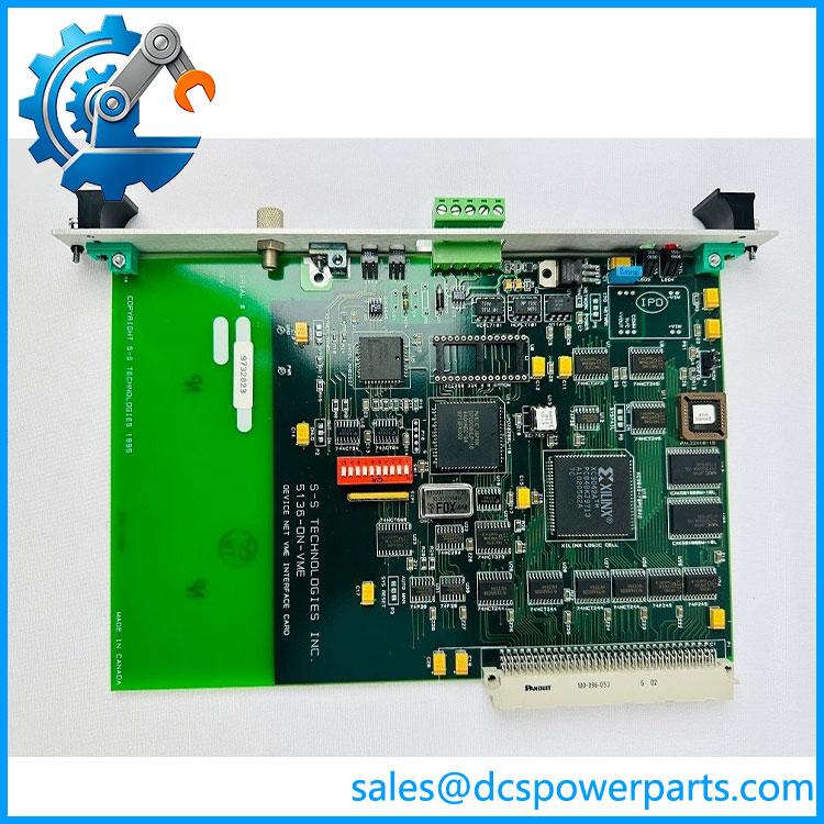
5136-DN-VME
Major Features / Practical Advantages
Dedicated onboard processing
The 5136-DN-VME is not simply a VME-to-CAN electrical converter. Its 16 MHz V40 processor executes application software modules stored in or downloaded to the card. This architecture reduces the amount of low-level CAN/DeviceNet processing that the host VME application has to perform.
The practical implication is straightforward: the application module is part of the replacement equation. A board that passes a basic hardware test can still fail to reproduce the original system behavior if the required application image is missing or incorrect.
DeviceNet and general CAN capability
The interface supports CAN specification 2.0A/B and CAN communication up to 1 Mbaud. For standard DeviceNet installations, the documented rates are 125, 250, and 500 Kbaud. The optically isolated CAN interface provides separation between the VME-side electronics and the network interface.
Configurable VME integration
Hardware switches configure the short-address control-register base address, access privileges, and VME interrupt level. The standard 128 KB RAM address can be selected through software. Interrupt levels 1 through 7 can be selected, or interrupts can be disabled in favor of polling.
This is one area where a replacement card should not simply be installed using factory-default switch positions. Compare the original board’s SW1 configuration with the host controller documentation before startup.
Optional EPROM boot configuration
An optional 27C512 EPROM can contain the application module. With the jumper in EPROM mode, the host does not download the application module during startup. This feature was intended for VME environments where normal application downloading is inconvenient or unavailable.
For maintenance teams, this creates an important inspection point: check whether the original board uses RAM-loaded software or an EPROM-based application before ordering a replacement.
External network termination
The 5136-DN-VME does not include an onboard DeviceNet termination resistor. When the card is located at the end of the DeviceNet trunk, the hardware reference calls for a 120-ohm termination resistor across the specified connector pins. CAN installations also require termination appropriate to the target CAN network.
That sounds minor, but missing termination can produce intermittent communication faults that look like a defective interface card. Check the physical network before condemning the VME board.
Related Products
- SST-DN3-VME-1 — Later SST DeviceNet VME interface associated with the 5136-DN-VME family. Omron documentation identifies it as the successor when a VMEbus-based DeviceNet solution is retained. Application compatibility still requires verification.
- 5136-DN-ISA — SST DeviceNet interface for ISA-bus systems rather than VMEbus systems.
- 5136-DN-PC — DeviceNet scanner/interface for PC-based architectures.
- 5136-DN-PCM — PCMCIA implementation of the SST DeviceNet interface family.
- 5136-DN-104 — PC/104 version for embedded computer applications.
- 5136-DNP-PCI — DeviceNet Pro PCI interface for newer PC architectures.
- 5136-MOD-VME — SST VME interface for Modicon Remote I/O; different protocol and application from the 5136-DN-VME.
- 5136-PBMS-ISA — SST PROFIBUS multi-slave ISA interface; not a DeviceNet replacement.
- 5136-REL-VME — SST VME interface for Reliance AutoMax DCS/RIO applications; different network function.
The 5136 family contains several bus and protocol variants that can look similar in inventory systems. Matching only the “5136” prefix is not sufficient. The complete suffix determines the host bus and network function.
FAQ
What is the SST 5136-DN-VME used for?
It provides a VMEbus-based computer or controller with an interface to DeviceNet and other CAN-based networks. It is a communication/interface card, not a conventional PLC CPU or discrete I/O module.
Does the 5136-DN-VME support standard DeviceNet speeds?
Yes. The hardware supports DeviceNet data rates of 125, 250, and 500 Kbaud. The underlying CAN interface supports rates up to 1 Mbaud.
Can I hot-swap this card?
Do not assume hot-swap capability. The hardware reference describes installation in a VME system but does not establish a hot-replacement procedure or hot-swap certification. Shut down or otherwise isolate the VME system according to the host chassis manufacturer’s procedure before removing the board.
Does the card contain its own processor?
Yes. The documented hardware contains a 16 MHz V40 microprocessor and 128 KB RAM. The processor executes downloadable application modules.
Does the 5136-DN-VME include the DeviceNet application software?
Not necessarily. The hardware reference explicitly describes application modules as separate software components that can be downloaded to the card. An optional EPROM can also contain an application module. Therefore, procurement should verify the required application image rather than treating the PCB part number as the complete software configuration.
Does it have an onboard DeviceNet termination resistor?
No. The manual explicitly states that the card does not contain a built-in termination resistor. A 120-ohm resistor is required at the appropriate end of a DeviceNet network.
What should I verify before replacing an installed 5136-DN-VME?
At minimum, verify:
- Exact board part number and hardware revision.
- Existing application-module type and version.
- EPROM versus RAM-loaded application configuration.
- SW1 VME address and interrupt settings.
- VME host hardware and operating environment.
- DeviceNet baud rate.
- Network node/application configuration.
- Connector type and field wiring.
- Required network termination.
- Host-side software interface and configuration files.
A replacement board can be electrically healthy yet fail system commissioning because one of these legacy configuration dependencies was overlooked.
Is there a direct replacement for the 5136-DN-VME?
Omron documentation identifies the SST-DN3-VME-1 as the successor when continuing to use a VMEbus DeviceNet interface. It should not be treated as an automatic drop-in replacement without checking the application software and host-side integration.
Procurement Note
The SST 5136-DN-VME is a legacy VME communication card, so procurement should focus on configuration retention rather than board appearance alone. The original SST documentation dates from 1999, and the product architecture depends on separately loaded application modules.
For a replacement unit, request clear photographs of the complete PCB, connector area, EPROM area, identification label, and revision markings where practical. If the existing installation is still operational, record the VME switch settings and application-module information before removing the failed card.
For New Surplus inventory, do not equate unused shelf condition with guaranteed system compatibility. Verify the board’s power-up diagnostics, RAM operation, CAN interface, connector condition, and availability of the required application software. For a used card, a functional test should include VME access, application startup, CAN/DeviceNet communication, and error-state verification rather than a simple visual inspection.
The manufacturer documentation also provides explicit diagnostic categories for RAM, CAN controller, NVRAM, application initialization, checksum, and interrupt faults. Those diagnostics are useful when qualifying a replacement before putting it into a production VME chassis.
Bottom line: the 5136-DN-VME is a specialized VME-to-DeviceNet/CAN interface, not generic VME I/O. Match the complete hardware, application module, VME configuration, and network configuration before declaring a replacement equivalent.