Description
Product Overview
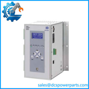
The SIGMATEK DPS001 is a power supply module designed for the DIAS industrial automation system. Its primary role is to provide the operating voltage required by a connected CPU without an internal power supply and to supply the DIAS bus for the associated modules. The unit accepts an input voltage of 18–30 V DC and provides a DIAS bus supply rated between +5.0 and +5.35 V DC. This makes it a power-system component rather than a digital input, digital output, or signal-processing module. Correct identification matters when diagnosing controller startup failures, unexplained module resets, or power-related interruptions in an established machine control cabinet.
Within a DIAS configuration, the SIGMATEK DPS001 supports the CPU and connected modules within a specified current budget. The manufacturer lists a maximum total current of 1.3 A for connected DIAS modules, with approximately 600 mA allocated to the CPU. Actual suitability therefore depends on the installed module combination and its load requirements; the input-voltage range alone does not establish compatibility. Two green status indicators provide basic visual checks: one identifies the +24 V supply status, while the other indicates DC output status. The module has no fiber-optic connections, so it should not be selected as a communication interface or bus converter.
For maintenance teams managing legacy DIAS-based machinery, the SIGMATEK DPS001 can serve as a direct replacement candidate when the existing module’s identification and electrical requirements match. Before installation, verify the complete part number, hardware revision, cabinet wiring, CPU arrangement, and total bus current. A replacement should also be inspected for connector damage, corrosion, and evidence of previous overheating. These checks help distinguish a genuine power-supply fault from a downstream short circuit or excessive module load. The SIGMATEK DPS001 should be treated as one part of the complete power-distribution design, not as a universal substitute for every DIAS power component.
Product Introduction (Non-Templated)
An unstable DIAS bus can interrupt CPU operation even when the cabinet’s incoming DC supply appears normal. The SIGMATEK DPS001 addresses the power-supply role in configurations that require an external CPU supply, accepting 18–30 V DC and delivering +5.0 to +5.35 V DC to the DIAS bus.
For a DIAS system repair or legacy replacement, verify the 05-002-001 part number and confirm that connected-module current remains within the 1.3 A limit. This check helps reduce avoidable commissioning delays.
Key Technical Specifications
| Parameter | Value |
|---|---|
| Manufacturer | SIGMATEK |
| Product Model | DPS001 |
| Manufacturer Part Number | 05-002-001 |
| Product Series | DIAS |
| Product Type | Power supply module |
| Hardware Version | 1.0 |
| Input Voltage | 18–30 V DC |
| Input Current Consumption | Load-dependent; maximum 1 A |
| DIAS Bus Output Voltage | +5.0 to +5.35 V DC |
| Maximum Total Current for Connected DIAS Modules | 1.3 A |
| CPU Current Allocation | Approximately 600 mA |
| Status Indicators | Green +24 V OK and DC OK LEDs |
| Fiber-Optic Connections | None |
| Product Standard | UL (E247993), as listed in manufacturer documentation |
| Application | DIAS CPU and bus power supply |
Source: SIGMATEK DPS 001 manufacturer technical documentation.
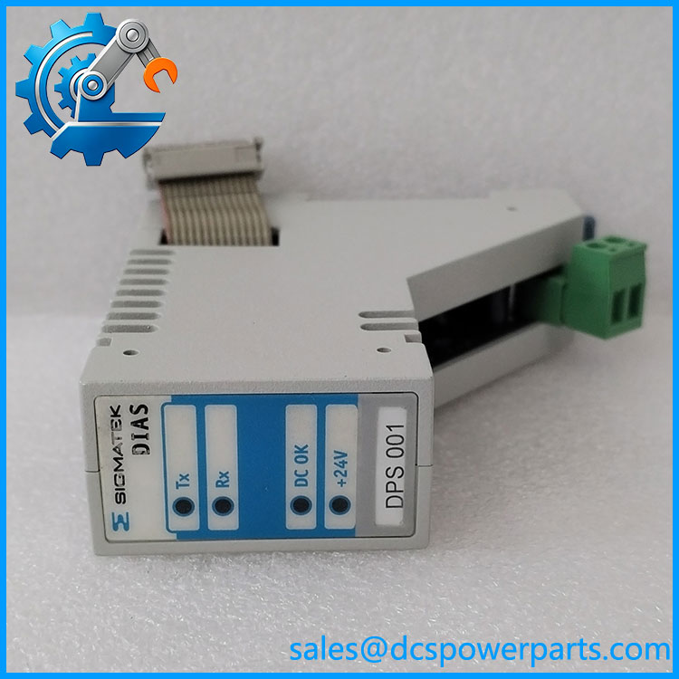
DPS001
Related Products
The following DIAS components may be relevant when maintaining or expanding a SIGMATEK automation installation. Confirm the specific system generation, hardware revision, connector arrangement, and compatibility requirements before treating any component as a direct substitute or companion part.
1. DCP643 — A DIAS CPU model referenced in DIAS system component listings. Relevant when investigating controller-side power requirements or planning a controller replacement. Confirm the exact CPU configuration before pairing it with the .
2. DNC115 — A DIAS CPU and Ethernet bus-coupling product identified in product listings. Its controller and communication functions differ from the ‘s power-supply role; verify the intended system architecture before selecting it.
3. DDM163 — A DIAS-family model referenced in system component listings. Confirm its exact function, current demand, and hardware compatibility from its own product documentation before including it in a bus-load calculation.
4. DNC031 — Another DIAS system component referenced in the same component listings. Establish whether the installed version performs the required processing or communication task before specifying it for a repair.
5. DKL003 — A model identified in DIAS system component listings. Verify its function and electrical requirements against the machine’s existing configuration; the model number alone does not establish direct compatibility with the .
6. DKL014 — A DIAS-associated component referenced in system listings. Consider it only after confirming its role in the target system and checking the available power budget.
7. DKL031 — A further DIAS-family component listed alongside other system modules. Its application should be established from the relevant hardware documentation rather than inferred from the shared product family.
8. DPB021 — A SIGMATEK DIAS-family digital input module described as a 16-channel, 24 V DC input unit. It serves field-signal acquisition rather than power conversion, so it is relevant when reviewing the I/O configuration and overall bus load.
Frequently Asked Questions (FAQ)
1. Is the SIGMATEK compatible with my existing DIAS controller?
Compatibility depends on the exact CPU and DIAS hardware configuration. The is intended to supply a connected CPU that lacks an internal power supply and provide power to the associated DIAS bus.
Before ordering, check:
- The installed module’s full part number and hardware version.
- The CPU’s power-supply requirements.
- The total current required by all connected DIAS modules.
- The wiring and physical installation arrangement.
A matching model number is an important starting point, but it does not replace a configuration check.
2. Can I hot-swap the while the PLC is running?
Do not assume that hot-swapping is supported. The available manufacturer documentation identifies the as a power supply module but does not establish that live removal or insertion is permitted.
For a planned replacement, use this procedure:
- Place the machine in a safe state.
- Follow the equipment manufacturer’s shutdown and isolation instructions.
- Verify that the relevant power sources are isolated.
- Replace and inspect the module, then restore power according to the site’s commissioning procedure.
- Confirm the +24 V OK and DC OK indicators and verify CPU and I/O operation.
If uninterrupted operation is mandatory, obtain explicit confirmation of the permitted replacement procedure for the complete installed system before attempting the work.
3. Does the support firmware v3.1?
The is documented with hardware version 1.0. The available product specification does not establish a firmware version 3.1 requirement or compatibility claim.
For engineering purposes, distinguish between the power module’s hardware revision and the firmware running on the connected controller. Verify the CPU model, controller firmware, and system documentation if a proposed upgrade includes changes to the control platform. Do not infer firmware compatibility from the model number alone.
4. Will replacing the erase my PLC program or control logic?
The supplies power; it is not identified as the controller’s program-storage module. Its replacement is not, by itself, a programming operation.
However, a power interruption may stop the controller and affect machine operation. Before maintenance:
- Confirm that the control program and relevant configuration files are backed up.
- Check how the installed CPU retains its program and operating data.
- Record any required startup and recovery procedures.
- Verify the program state, I/O operation, and machine interlocks after power is restored.
Program retention depends on the controller and its configuration, not solely on the power module.
5. How can I verify that a new-surplus is genuine?
A new-surplus description indicates inventory status, not automatic proof of authenticity or unused condition. Ask for evidence tied to the actual unit being supplied.
Recommended checks include:
- Confirming the SIGMATEK identification and part number 05-002-001.
- Comparing the hardware-version marking with the order specification.
- Inspecting connectors, terminals, housing, and labels for damage or signs of rework.
- Requesting current photographs and documented functional-test results.
- Confirming that the stated condition and warranty appear on the quotation or order confirmation.
To be completely transparent, packaging alone cannot establish that a module is genuine or electrically functional.
6. What should I check if the ‘s DC OK LED does not illuminate?
Start with the incoming supply and the connected load rather than immediately assuming that the module has failed.
| Check | What to investigate |
|---|---|
| Input supply | Confirm that the measured DC voltage is within 18–30 V DC. |
| Wiring | Inspect polarity, terminals, and connections against the approved wiring diagram. |
| Connected load | Check for a short circuit, excessive current demand, or a faulty downstream module. |
| Status indicators | Observe both +24 V OK and DC OK indicators and record their behavior. |
| Replacement decision | Test or substitute the module only after following the equipment’s isolation and diagnostic procedures. |
The ‘s documented maximum total current for connected DIAS modules is 1.3 A. A downstream load problem can therefore be relevant even when the incoming supply voltage appears correct.
7. What warranty applies to the SIGMATEK , and can it be returned if it fails testing?
Warranty coverage depends on the seller’s written terms and the specific unit supplied. Do not assume that a new-surplus unit carries the same warranty as a newly manufactured unit purchased directly from the original manufacturer.
Before purchase, obtain written confirmation of:
- The warranty period and coverage for functional failure.
- Whether the unit is tested before dispatch.
- The available inspection or acceptance period after delivery.
- The procedure for reporting faults and arranging repair or replacement.
- Any exclusions for incorrect installation, electrical damage, or unauthorized repair.
For production-critical equipment, request documented test results and confirm the return procedure before authorizing the order. This provides a clearer basis for evaluating the replacement risk than condition labels alone.