Description
Product Overview
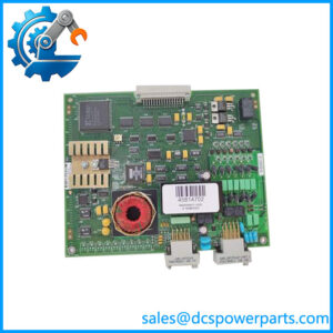
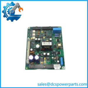
The Reliance Electric 0-60031-6 Resolver and Drive I/O Module is a feedback and interface board used in compatible AutoMax and Power Module Interface (PMI) drive architectures. Its role involves handling resolver feedback and drive I/O signals, allowing the PMI control system to use motor feedback information as part of drive control. This makes the module relevant to industrial AC and DC drive installations that depend on the original Reliance Electric control architecture.
The board has two primary front-panel connectors: P1, labeled FEEDBACK, and P2, labeled I/O. Its status indicators include FDBK OK, RPI, MCR, AUX IN1 through AUX IN5, and AUX OUT. These indicators provide diagnostic clues during troubleshooting, although their exact meanings and expected states should be confirmed in the applicable system documentation. The Reliance Electric 0-60031-6 also has a rear multi-pin connection for installation into the compatible rack or assembly.
For maintenance teams supporting legacy drive equipment, replacing this board requires more than matching the general product description. Verify the full part number, board revision, connector arrangement, and associated PMI processor. Resolver wiring, feedback scaling, and drive configuration must also be checked before returning the equipment to service. The Reliance Electric 0-60031-6 is identified as a legacy, obsolete part, so buyers should establish the supplied unit’s condition and obtain clear evidence of functional testing before installation.
Product Introduction (Non-Templated)
When a drive reports a feedback fault, the cause may lie in the resolver, field wiring, interface board, or downstream control configuration. The 0-60031-6 combines resolver-feedback and drive-I/O interfaces in one PMI-related assembly, making correct identification important during fault isolation.
Before replacing the board, document the original connector positions and status-indicator conditions. Inspect the rear rack connector and confirm the replacement revision against the installed hardware. Do not treat a matching faceplate as proof of electrical compatibility.
Key Technical Specifications
| Parameter | Value |
|---|---|
| Product Model | 0-60031-6 |
| Manufacturer / Brand | Reliance Electric |
| Product Family | AutoMax / PMI drive control |
| Product Type | Resolver and drive I/O module |
| Primary Function | Resolver feedback processing and drive I/O interfacing |
| Connector P1 | FEEDBACK |
| Connector P2 | I/O |
| Status Indicators | FDBK OK, RPI, MCR, AUX IN1–AUX IN5, AUX OUT |
| Rack Interface | Rear multi-pin connector |
| Compatible System | Applicable Reliance Electric AutoMax / PMI drive architecture |
| AC/DC Drive Use | Reported for compatible AC and DC drive applications; verify the specific system |
| Supply Voltage | Not verified |
| Resolver Input Ratings | Not verified |
| Digital I/O Electrical Ratings | Not verified |
| Communication Protocol | No standard fieldbus protocol verified |
| Operating Temperature | Not verified |
| Mounting | Compatible PMI rack or assembly |
| Protection Rating | Not verified |
| Product Status | Legacy / obsolete |
| Firmware / Revision | Confirm from the physical board and system documentation |
The available product references support the module’s functional description, connectors, and indicator labels. Voltage, signal thresholds, environmental limits, and detailed electrical ratings should be taken from the correct technical documentation rather than estimated.
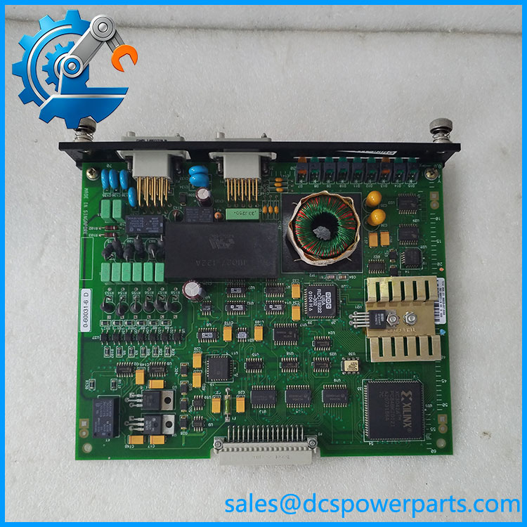
0-60031-6
Related Products
These components are associated with the broader Reliance Electric AutoMax/PMI drive architecture. Their functions differ, and they should not be considered direct substitutes without documentation.
- 0-60031-4 — Related AutoMax resolver/drive I/O module; verify revision and interface differences.
- 0-60031-5 — Resolver and drive I/O PMI module in the same general product family.
- 0-60021-4 — PMI processor module responsible for drive-control processing.
- 0-60002-6 — DC Power Technology module used in compatible DC drive configurations.
- 0-60007-3 — DC power supply board associated with the drive system.
- 0-60002-5 — DC Power Technology module with a different drive-interface role.
- 0-60023-5 — AC Power Technology module for applicable AC drive configurations.
- 0-60028-2 — Gate driver interface module serving a different drive-control function.
The model-family descriptions are based on available parts references. Check the complete system bill of materials and hardware revision before selecting related parts.
Frequently Asked Questions
1. What is the Reliance Electric 0-60031-6 used for?
It is a resolver and drive I/O module used in compatible AutoMax/PMI drive systems. It interfaces resolver feedback and drive I/O signals with the surrounding control architecture.
2. Can I replace a 0-60031-5 with a 0-60031-6?
Do not assume interchangeability. Although both are associated with resolver and drive I/O functions, the exact board revision, electrical interfaces, and application compatibility must be verified before substitution.
3. Can I hot-swap this module?
Do not assume hot-swap support. Follow the applicable drive shutdown procedure, isolate hazardous power, and observe electrostatic-discharge precautions. Confirm the machine is in a safe state before removing the module.
4. Does the 0-60031-6 support firmware v3.1?
A firmware version v3.1 has not been verified for this board. Check whether the version refers to the PMI processor, drive software, or another component. Confirm the relevant hardware and software revisions before updating the system.
5. What do the FDBK OK and AUX status LEDs indicate?
The labels identify feedback and auxiliary I/O status points. Their precise meanings, normal states, and fault interpretations depend on the drive configuration and documentation. Record the LED pattern during the fault and compare it with the applicable troubleshooting instructions.
6. How can I verify that a replacement is compatible?
Match the complete 0-60031-6 part number, revision markings, P1 and P2 connector layout, rear rack connector, and associated PMI hardware. Also verify resolver wiring and drive configuration. Do not rely on appearance alone.
7. What should I request when buying a refurbished module?
Ask for clear photographs of both sides of the board, connector condition, visible revision markings, functional test scope, warranty terms, and known limitations. Where possible, request test evidence showing that feedback and I/O functions were checked. A clean board or powered indicator alone does not establish full functionality.
Procurement recommendation: For a legacy replacement, confirm the complete board number and revision against the removed module, then establish the condition and test scope of the supplied unit. This reduces the risk of installing a physically similar board with an incompatible interface or unverified operating condition.