Description
Product Overview
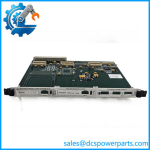
In an established marine automation installation, a control-board fault can interrupt equipment monitoring or local control even when the rest of the system remains serviceable. The NORIS SA648-1G is a control printed circuit board associated with the NORIS N3000 automation platform. N3000 system drawings show the SA648-1G at the power-unit position within an I/O assembly, while available part information identifies a 24 VDC rating and a Rev. B variant. These references establish its system association, but the exact electrical role should be confirmed against the specific cabinet drawing and board markings before replacement.
The NORIS N3000 platform uses modular I/O assemblies with separate cards for control, signal acquisition, and output functions. In this architecture, the SA648-1G should be evaluated as part of the complete assembly rather than as a standalone PLC power supply. Confirm the incoming supply arrangement, connector positions, board revision, and related I/O cards before approving a substitute. A nominal 24 VDC designation alone does not establish acceptable voltage tolerance, current capacity, isolation behavior, or compatibility with every N3000 configuration. Where the board supports a vessel’s engine-monitoring or machinery-control installation, a wrong replacement can create additional commissioning work or leave local functions unavailable.
For maintenance procurement, match the complete SA648-1G designation and revision to the installed hardware. Record the original fault symptoms, inspect connectors for heat damage or corrosion, and request inspection or functional-test evidence for the replacement unit. If the board is being sourced as new surplus, verify its actual condition rather than relying on the stock description. These checks help limit avoidable downtime and preserve the existing N3000 system configuration.
Product Introduction (Non-Templated)
When an N3000 I/O assembly develops a board-level fault, replacing the correct PCB is usually preferable to changing unrelated control hardware. The NORIS SA648-1G is identified as a control PCB associated with the system, with a reported 24 VDC rating.
For a legacy replacement, match the board revision, connector layout, and cabinet wiring before installation. The available documentation does not establish a universal drop-in replacement or a verified current rating.
Key Technical Specifications
| Parameter | Value |
|---|---|
| Product Model | SA648-1G |
| Manufacturer | NORIS Automation |
| Product Type | Control PCB |
| Product Series | |
| Reported Supply Voltage | 24 VDC |
| Reported Revision | Rev. B |
| System Application | modular I/O assembly |
| Board Position | Power-unit position shown in an system drawing |
| Current Capacity | Not verified |
| Power Consumption | Not verified |
| Operating Temperature | Confirm against the applicable hardware documentation |
| Communication Interface | Not verified for this specific PCB |
| Installation Method | Installed in the compatible assembly |
| Protection Rating | Depends on the installed assembly |
| Firmware Compatibility | Confirm against the system configuration |
| Condition | Must be confirmed for the supplied unit |
The voltage and revision details are reported in available part information. The board position is based on an arrangement drawing; confirm both against the actual equipment documentation.
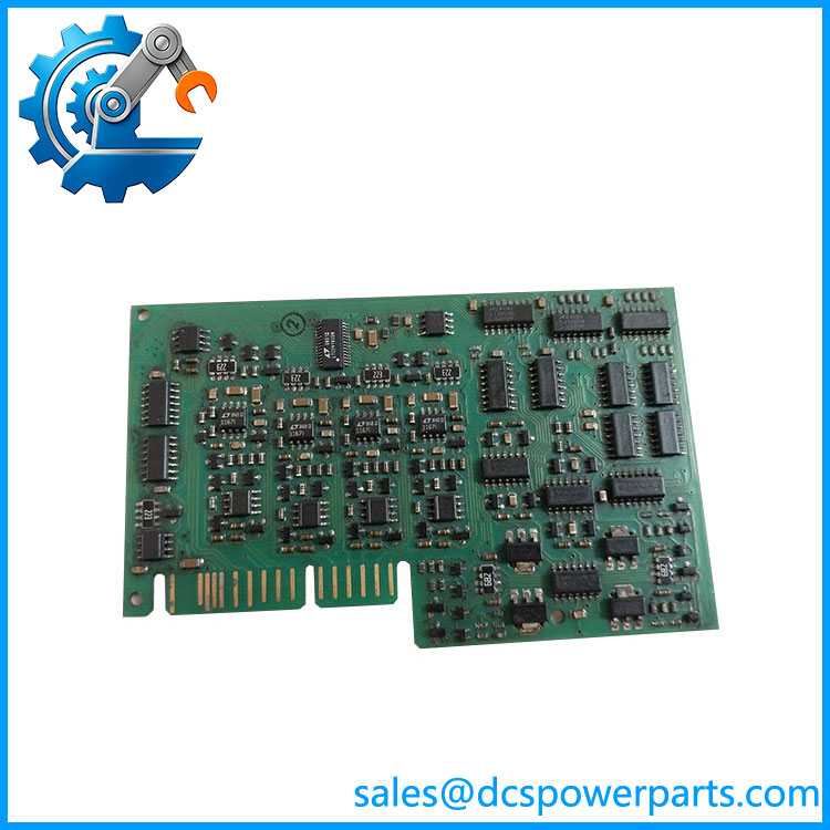
SA647-1G
Related Products
These NORIS components are associated with the system. Their functions differ, so none should be treated as a direct replacement without documented compatibility.
SA647-2G
Analog input module identified in equipment documentation. Consider it when servicing sensor-input channels, not as a substitute for the control PCB.
SA655-42G
input/output module used for signal handling. Its purpose is field I/O rather than the control-board or power-unit position associated with the .
SA646-20G
Main plug-in board specified for the master cabinet. Its cabinet-level role differs from that of the .
SA646-21G
Main plug-in board listed for the slave cabinet. Check cabinet designation and system drawings when identifying the required replacement.
SA650-31G
Master control PCB specified in equipment documentation. It has a different control-system role and should not be substituted for the solely on the basis of series membership.
-DSP
Display unit used in NORIS control-system installations. It supports operator indication and monitoring rather than replacing the control PCB.
Frequently Asked Questions (FAQ)
1. Is the NORIS compatible with every system?
No universal compatibility claim can be made from the model number alone. assemblies vary in their board arrangement and application.
Before ordering, compare the original part number, board revision, cabinet drawing, and connector configuration. Confirm that the intended installation uses the in the same position.
2. Does the operate on 24 VDC?
Available part information reports a 24 VDC rating. However, the allowable voltage range, current capacity, and any required upstream protection have not been verified.
Use the electrical specifications for the exact board revision when checking supply compatibility. Do not infer a permissible voltage range from the nominal rating alone.
3. Can I hot-swap the while the system is running?
Do not assume that live replacement is supported. The available references do not confirm a hot-swap function for this PCB.
Use the approved isolation procedure and establish which monitoring, alarm, or control functions could be interrupted before removing the board. Live replacement should only be considered if the applicable OEM documentation explicitly permits it.
4. Will replacing the erase my PLC or DCS logic?
The answer depends on the system architecture and where its application data is stored. The available information does not establish whether this PCB stores user logic or configuration data.
Recommended procedure:
- Back up the available system configuration.
- Record board and firmware identification.
- Document the original fault condition.
- Follow the approved replacement and commissioning instructions.
- Verify affected functions after power-up.
5. How can I verify that a new-surplus is genuine and unused?
A new-surplus description is not proof of authenticity or factory-sealed condition. Request photographs of the actual board, its labels, revision markings, and connectors. Ask for the inspection history and functional-test records where available.
If the unit has been opened, stored for an extended period, or previously installed, that information should be disclosed rather than describing it as factory sealed without evidence.
6. What should I check if the replacement does not restore system operation?
Start by checking the installation rather than assuming the replacement PCB is defective.
- Confirm that the board is the correct revision.
- Check the supply against the specified electrical limits.
- Inspect connectors and the mating board or backplane.
- Review system alarms and fault indications.
- Verify related I/O modules and cabinet wiring.
If the same fault persists, investigate the surrounding assembly and supply path before replacing additional components.
7. What warranty should I expect when purchasing an replacement?
Warranty terms depend on the supplier and the condition of the unit. The model number does not establish a specific warranty period.
Obtain written confirmation of the coverage period, whether functional failure is covered, the return procedure, and any exclusions. For marine or machinery-control applications, request the available inspection and test records before accepting the replacement.