Description
MTL 8701-CA-BI | Redundant BIM Carrier | PAC8000 PROFIBUS-DP
Key Technical Specifications
| Parameter | Specification |
|---|---|
| Manufacturer | MTL / Emerson |
| Model | 8701-CA-BI |
| Product Family | / MTL8000 |
| Product Type | Redundant BIM Carrier |
| BIM Capacity | 2 modules |
| Compatible BIM | 8507-BI-DP |
| Communication | PROFIBUS-DP |
| PROFIBUS Ports | 2 × 9-pin D-sub female |
| Railbus Connector | Male output |
| External DC Supply | 12 VDC ±5% |
| Power Supply Options | 2 × 8910-PS-DC or external BQ2320-9R-EX arrangement |
| Power-Fail Detection | Supported |
| Ground Terminals | 2 × M4 screw terminals |
| Operating Temperature | -40°C to +70°C |
| Storage Temperature | -40°C to +85°C |
| Relative Humidity | 5–95% RH, non-condensing |
| Mounting | DIN rail or flat panel |
| Dimensions | 178 × 170 × 68 mm |
| Weight | Approximately 450 g |
| Hazardous-Area Location | Zone 2, IIC T4, subject to installation conditions |
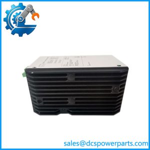
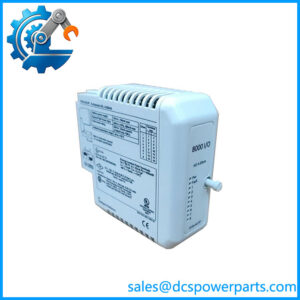
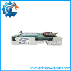
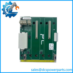
The MTL documentation identifies 8701-CA-BI as a redundant BIM carrier designed to accommodate two Bus Interface Modules. It provides dual PROFIBUS network connections and supports DIN-rail or panel mounting.
Product Introduction
The MTL 8701-CA-BI is a carrier designed specifically for redundant Bus Interface Module installations. Unlike an individual I/O module, the carrier provides the physical and electrical interface for two 8507-BI-DP PROFIBUS-DP BIMs. Each BIM can operate in parallel, allowing the standby unit to monitor the active unit and support continued communication in applications where network availability is important.
The Emerson 8701-CA-BI therefore belongs to the communication infrastructure of a remote I/O node rather than the field-signal layer. The carrier provides two PROFIBUS connections, Railbus interconnection, power-supply monitoring, grounding provisions, and the mechanical interface required by the redundant BIM pair.
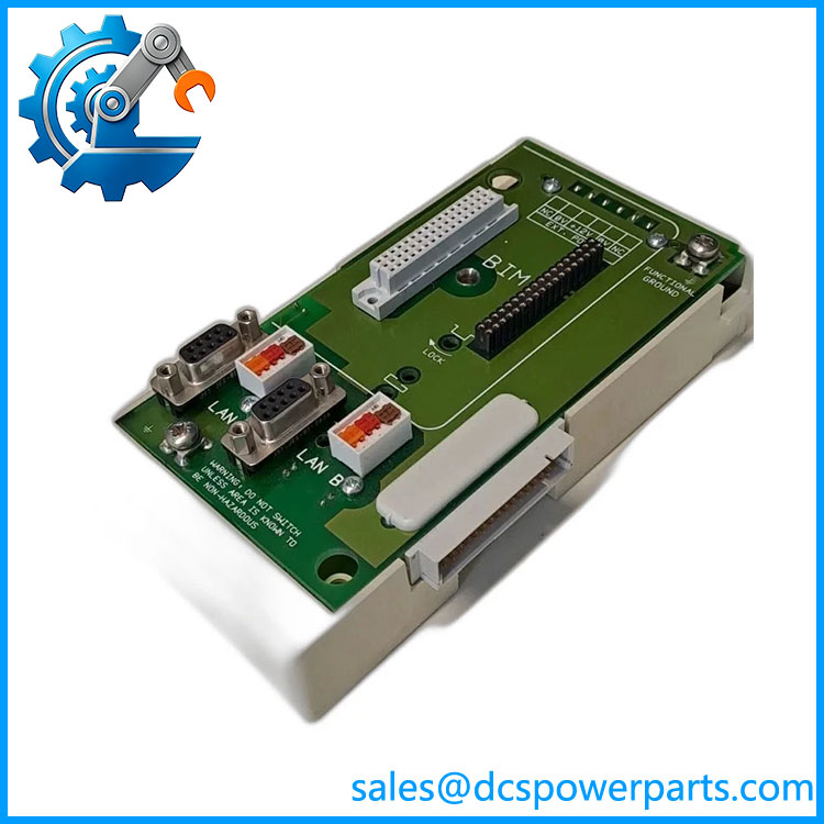
8701-CA-BI
Application Scenarios & Field Pitfalls — The Engineer’s Perspective
Engineering Pain Point
When a PROFIBUS node loses communication, replacing the BIM immediately is not always justified. The 8701-CA-BI sits between the BIMs, power arrangement, Railbus, and PROFIBUS network. A carrier connector, power-supply failure, grounding issue, or PROFIBUS wiring fault can produce symptoms that look like a failed communication module.
Typical Applications
1. Redundant PROFIBUS-DP remote I/O
The carrier is designed for two 8507-BI-DP modules and provides two PROFIBUS network connections. The 8507-BI-DP acts as the PROFIBUS slave interface between I/O modules and the PROFIBUS master.
2. Critical process-control nodes
Redundant BIM operation is intended for installations where loss of a single communication interface should not unnecessarily interrupt the remote I/O node. Each BIM operates in parallel and monitors the status of the other.
3. distributed I/O
The carrier forms part of the communication side of a I/O installation, connecting the I/O subsystem to the PROFIBUS-DP host through the installed BIMs.
4. Hazardous-area control installations
The published carrier specification identifies Zone 2, IIC T4 hazardous-area application, subject to the applicable installation conditions and approved system configuration.
Technical Pitfalls
Do not treat 8701-CA-BI as an ordinary I/O carrier.
The 8701-CA-BI is a Multi-BIM carrier. It is specifically intended for two 8507-BI-DP PROFIBUS-DP BIMs. It is not equivalent to the 8707-CA-08 eight-module I/O carrier.
Verify the BIM model.
The documented BIM associated with this carrier is 8507-BI-DP. The BIM provides the PROFIBUS-DP communication function; the 8701-CA-BI itself does not replace the BIM’s communication electronics.
Check both PROFIBUS connections.
The carrier provides two 9-pin D-sub female PROFIBUS connections. If redundancy is being used, both network paths should be checked for correct wiring, termination, addressing, and master configuration.
Inspect the power architecture.
The carrier supports two 8910-PS-DC supplies, while current documentation identifies the 8910-PS-DC as obsolete and gives BQ2320-9R-EX as an alternative external power supply arrangement. The replacement supply requires its separate mounting kit.
Use the power-fail diagnostics correctly.
The carrier reports power-supply failures to the BIMs. External power-fail signals can also be connected through the carrier’s 8-pin connector. This makes the carrier power circuit part of the communication troubleshooting path.
Check environmental requirements.
The published operating range is -40°C to +70°C, with storage from -40°C to +85°C and 5–95% non-condensing humidity. Actual hazardous-area installation must still satisfy the applicable approval and installation requirements.
Do not assume any two BIMs can be installed.
The carrier is documented around the 8507-BI-DP architecture. Other network interface modules use different carrier arrangements. For example, current product information distinguishes the 8701-CA-BI from 8715-CA-BI and 8718-CA-NS carriers used with other BIM families.
Related Products
- MTL 8507-BI-DP — PROFIBUS-DP Bus Interface Module installed on the 8701-CA-BI.
- MTL 8507-BI-DP Redundant Pair — two BIMs used together for redundant operation.
- MTL 8707-CA-08 — 8-module carrier for standard I/O modules.
- MTL 8709-CA-08 — 8-module carrier for 64-address systems.
- MTL 8710-CA-04 — 4-module carrier.
- MTL 8715-CA-BI — BIM carrier for other network interface configurations.
- MTL 8718-CA-NS — BIM and Node Services carrier supporting PROFIBUS/Modbus configurations.
- MTL 8727-CA-08 — intrinsically safe 8-module carrier.
- MTL BQ2320-9R-EX — alternative external DC power supply arrangement documented for the 8701-CA-BI.
- MTL BQ2320-ACC — mounting kit associated with the external BQ2320-9R-EX power supply arrangement.
Procurement Note
When sourcing an 8701-CA-BI, match the exact carrier designation and verify that the existing node uses 8507-BI-DP PROFIBUS-DP BIMs. Confirm the two BIM positions, PROFIBUS connectors, Railbus connection, grounding, and power-supply arrangement before installation.
For used or surplus hardware, inspect the BIM connectors, PROFIBUS D-sub sockets, Railbus interface, power-supply contacts, grounding terminals, and carrier PCB for corrosion or heat damage. If only one of the redundant BIM paths is communicating, test the carrier and both power paths before condemning either BIM.
Engineering classification: MTL / Emerson 8701-CA-BI — redundant Multi-BIM carrier for two 8507-BI-DP PROFIBUS-DP Bus Interface Modules.