Description
Product Overview
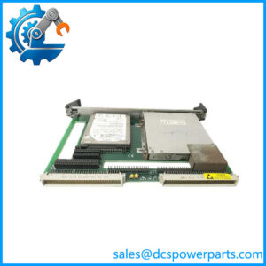
When an existing control system needs to generate multiple analog command signals, replacing its output hardware requires more than matching the connector and board dimensions. The GE VMIVME-4140 is a 32-channel, 12-bit analog output board designed for VMEbus-based industrial computing and control systems. Each channel has its own digital-to-analog converter (DAC), allowing the host processor to generate independent voltage signals for connected equipment. Typical applications include industrial control, data acquisition, precision signal generation, and automated test systems.
The board supports software-selectable unipolar ranges of 0 to +2.5 V, 0 to +5 V, and 0 to +10 V, as well as bipolar ranges of ±2.5 V, ±5 V, and ±10 V. Each output can source or sink up to 10 mA, with a specified output impedance of 0.8 ohms. Double-buffered output registers support software-triggered or externally synchronized updates, which can be useful when multiple command channels must change together. Automatic calibration and onboard self-test functions help maintenance personnel identify output problems without immediately removing the board from the system.
For engineers maintaining legacy VMEbus installations, the GE VMIVME-4140 remains relevant where the host computer, software drivers, and field wiring are built around its interface and register architecture. The product entered a restricted production phase in May 2019, so lifecycle planning and verification of replacement stock deserve attention.
Before installing a replacement, check the complete part number, board revision, VMEbus addressing jumpers, output voltage configuration, and cable termination method. Also verify the connected load’s voltage and current requirements. A board that passes a basic power-on test may still have an inaccurate or damaged output channel, so applications involving actuators or precision test signals should include channel-by-channel verification.
Product Introduction (Non-Templated)
A single failed analog output can disrupt a test sequence or leave a control channel without its required command signal. The GE VMIVME-4140 provides 32 independent 12-bit DAC channels for VMEbus-based control and data acquisition systems.
With selectable voltage ranges up to ±10 V and a maximum output current of 10 mA per channel, it supports a range of low-current analog signal applications. For a legacy VMEbus replacement, verify addressing, cable termination, and every required output range before returning the system to service.
Key Technical Specifications
| Parameter | Value |
|---|---|
| Product Model | VMIVME-4140 |
| Manufacturer / Brand | VMIC / GE Fanuc; product line later supported by Abaco Systems |
| Product Type | Analog Output Board |
| Bus Interface | VMEbus |
| Form Factor | 6U, single-slot VME board |
| Analog Output Channels | 32 |
| Resolution | 12 bits per channel |
| DAC Architecture | One DAC per output channel |
| Unipolar Output Ranges | 0 to +2.5 V, 0 to +5 V, 0 to +10 V |
| Bipolar Output Ranges | ±2.5 V, ±5 V, ±10 V |
| Maximum Output Current | 10 mA per channel, source or sink |
| Output Impedance | 0.8 Ω |
| Update Method | Random channel updates; double-buffered synchronous updates |
| Calibration | Automatic calibration initiated by reset or software command |
| Diagnostics | Onboard self-test and status indication |
| Field Wiring | Discrete-wire or mass-terminated cable options |
| Front Panel | Analog output connector, status LED, reference-voltage access |
| Power Supply | +5 VDC; confirm the exact current requirement from the applicable hardware manual |
| Operating Temperature | Confirm the applicable environmental specification for the installed revision |
| Production Status | Restricted Production Phase since May 31, 2019 |
| Condition | New surplus; actual packaging and test status must be verified |
Specifications are based primarily on the manufacturer’s product documentation. Confirm the hardware revision and manual before using these values for engineering acceptance.
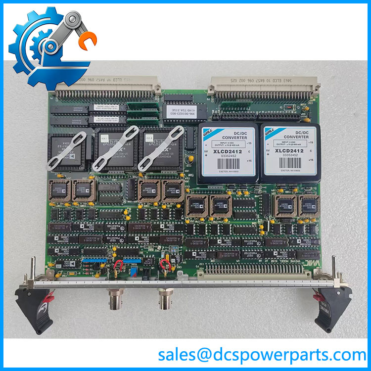
VMIVME-4140
Related Products
The following products and accessories are relevant to VMIVME-4140 installations. Some are supporting hardware rather than direct replacement boards.
- VMIVME-4140-001 — A related ordering designation appearing in product listings. Verify whether the suffix identifies a specific assembly revision or configuration before treating it as equivalent to .
- VMIVME-4145 — Investigate this model only if the application requires an alternative analog output architecture; verify its channel count, voltage ranges, and software compatibility before substitution.
- VMIVME-4116 — A related VMIC analog output product designation worth checking when evaluating alternative analog output hardware. Confirm the exact specifications and compatibility with the host system.
- VMIVME-4100 Series — Related VME analog I/O hardware to investigate for legacy system maintenance. Channel configuration and output behavior vary by model.
- VME-4140 Hardware Reference Manual — The key supporting document for board installation, VMEbus addressing, register programming, output configuration, and troubleshooting.
- VMIACC-BT04 — A related accessory designation listed in the manufacturer’s documentation. Confirm its exact function and cable compatibility before ordering it for a installation.
- VMIACC-BT10 — Another accessory designation listed in the product documentation. Verify its intended connection and termination arrangement against the installed board.
- VMEbus Host CPU Board — Provides the processor and software environment that accesses the through the VME backplane. Verify address decoding, bus access settings, and driver support.
- Mass-Terminated Output Cable Assembly — Supports grouped field wiring from the board’s output connector. Confirm pin assignments and cable configuration before reconnecting existing equipment.
- Discrete-Wire Output Cable Assembly — Suitable for installations using individual output wiring. Verify the connector type, channel mapping, and grounding arrangement against the original drawings.
These products are potential supporting or comparison items, not confirmed drop-in substitutes. Use the original bill of materials and hardware manual to establish compatibility.
Frequently Asked Questions (FAQ)
1. What is the GE analog output board used for?
The converts digital values supplied by a VMEbus host into analog voltage signals. Its 32 independent DAC channels support applications such as control-signal generation, automated testing, and data acquisition.
Each channel can be configured for a supported unipolar or bipolar voltage range. The connected equipment must accept the selected range and remain within the board’s 10 mA output-current limit.
2. Does the support ±10 V output?
Yes. The board supports software-selectable bipolar ranges of ±2.5 V, ±5 V, and ±10 V, along with three unipolar ranges.
Before connecting a field device:
- Confirm the required output range.
- Check whether the load needs sourcing or sinking current.
- Verify the 10 mA per-channel limit.
- Confirm the software configuration and output wiring.
A configured ±10 V range does not mean the board can drive loads that exceed its current capability.
3. Can the replace my existing VME analog output card?
Potentially, provided the replacement matches the original system’s hardware and software requirements.
Check the VMEbus form factor, board revision, address jumpers, register programming, output channel mapping, and cable termination. If the existing control software was written specifically for the , a different analog output board may require driver or application changes even when its electrical specifications appear similar.
4. Can I hot-swap the while the system is running?
Do not assume that live removal is supported. Removing an analog output board may interrupt all 32 channels and cause connected equipment to lose its command signals.
Follow the host system’s approved maintenance procedure. Determine whether the controlled equipment must be placed in a safe state and whether the VME chassis must be powered down before removing the board.
5. How do I test a before putting it back into service?
The manufacturer’s documentation identifies onboard self-test and automatic calibration capabilities. These features are useful, but they do not replace external verification of every required output.
A practical test sequence is:
- Inspect the board, connector pins, and address jumpers.
- Run the documented startup self-test and calibration procedure.
- Command representative values across each required voltage range.
- Measure the outputs with calibrated test equipment.
- Check synchronous updates and any channels used by critical control functions.
Record the measured results and compare them with the acceptance limits in the applicable manual.
6. Will replacing the erase my control logic?
The board is an output device, not the host computer that ordinarily stores and executes the application. Replacing the board would not normally erase software stored on the host CPU.
However, the host may require a specific driver, board address, and output configuration. Record the existing settings and confirm the application recognizes the replacement before restoring field control.
7. Is the GE still available as new surplus, and what warranty should I request?
The manufacturer lists the VME-4140 product line as having entered a Restricted Production Phase on May 31, 2019. That lifecycle status makes it important to verify the condition and provenance of any offered unit.
Before purchasing, request:
- Confirmation of the exact model and revision.
- Photographs of the actual board and its labels.
- A clear statement of whether the unit is unused, refurbished, or previously operated.
- Test results for the analog output channels and calibration functions.
- Written warranty coverage and return conditions.
For a control system that cannot tolerate an extended outage, confirm the board’s condition and test evidence before scheduling the replacement.