Description
Key Technical Specifications
| Parameter | Specification |
|---|---|
| Manufacturer | GE Multilin / GE Power Management |
| Model | MMI301 |
| System | DGP Digital Generator Protection |
| Module Type | Man-Machine Interface |
| Display | 16-character alphanumeric LED |
| Local Keypad | 20 keys |
| Status Indication | Dual-color relay-status LED |
| Local Communication | RS232 |
| Front PC Connector | 9-pin D-sub associated with MMI communication |
| Primary Functions | Fault reports, metering, alarms, settings, stored data |
| Installation | Plug-in DGP relay module |
| Associated Relay | GE Multilin DGP |
| Software / PC Interface | GE-Link / DGP-PC depending DGP generation |
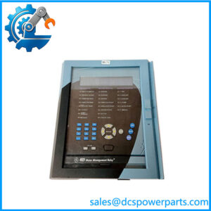
GE’s current DGP product documentation identifies the MMI301 as the local interface module and specifies a 16-character alphanumeric LED display, 20-key keypad, dual-color status indication, and RS232 connection.
The DGP architecture places MMI301 alongside modules such as SSP301, ANI301, DAP201, DSP401, DIT101, and MGM781. These are separate functional modules within the protection relay; MMI301 itself is not the protection processor or analog acquisition module.
Product Introduction
The GE Multilin MMI301 provides the local operator interface for the DGP Digital Generator Protection System. Through its LED display and keypad, operators and engineers can review fault reports, metering values, alarm information, protection settings, and stored relay information without relying solely on a remote workstation.
The module also provides an RS232 communication path for a local computer. DGP documentation identifies the front MMI communication connection as a 9-pin D-sub interface, while a separate rear DB-25 RS232 port is provided on the DGP enclosure for remote communications or station integration.
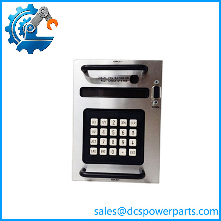
MMI301
Application Scenarios & Field Pitfalls — Engineer’s Perspective
Engineering Pain Point
MMI301 is easy to misidentify because the same model number appears in unrelated electronic-product searches. For the GE automation application, the important identification is as the DGP protection-system MMI module.
Typical Applications
- Generator protection panels — local viewing of protection status, metering, alarms, and trip information.
- Power-generation switchgear — local access to DGP relay settings and stored fault information.
- Legacy DGP maintenance — replacement of a failed display/keypad interface without replacing the complete protection relay.
- Commissioning and troubleshooting — local interaction with the DGP and PC-based communication through the MMI interface.
Technical Pitfalls to Avoid
- Do not confuse with the DGP processor.
The DGP uses separate SSP301, ANI301, DAP201, and DSP401 modules. provides the operator interface; it does not perform the main protection calculations. - Do not assume every RS232 port on the DGP serves the same purpose.
The MMI has its own front communication connection, while PL-1 on the rear provides another RS232 path for modem or station-integration applications. - Check the DGP hardware generation before replacement.
GE documentation lists as a replacement module across DGPxxxAAA, DGPxxxABA, and DGPxxxACA configurations. Firmware revision and complete DGP model should still be verified before installation. - Power down the relay before removing the module.
The DGP manual specifically warns that individual modules should not be replaced while the relay is energized; the relay should be powered down through the specified test plugs or power-supply switches before module replacement.
Related Products
- GE Multilin DGP — complete Digital Generator Protection System using the local interface.
- GE SSP301 — DGP system processor module.
- GE ANI301 — analog interface module within the DGP architecture.
- GE DAP201 — data acquisition module.
- GE DSP401 — digital signal processor module.
- GE DIT101 — digital input and target module.
- GE MGM781 — magnetic module containing CT, VT, and relay-interface functions.
- GE PS1 / PS2 — DGP power-supply modules; PS2 is optional depending on configuration.
- GE DEC1000 — contact expansion unit that can be connected through the applicable DGP serial interface on supported configurations.
Procurement Check
For a replacement, verify the complete DGP relay model, hardware revision, existing MMI module, display/keypad condition, communication connector, and firmware/software environment.
The key identification is:
→ DGP Man-Machine Interface
Display → 16-character alphanumeric LED
Keypad → 20 keys
Communication →
Application → GE Multilin DGP Digital Generator Protection System
Do not approve a listing simply because it describes as a generic HMI, Mark VI module, processor, or 24 VDC operator panel. GE’s DGP documentation gives a much more specific identity and function for this part.