Description
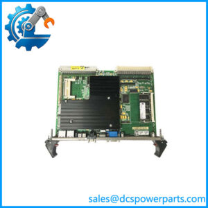
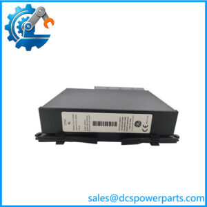
GE IS220PSVOH1A Servo Control I/O Pack
Product Introduction
A turbine servo loop is not an ordinary analog-output circuit. The control pack has to exchange data with the turbine controller, drive the servo-valve interface, excite and measure position feedback, and report diagnostic information without introducing an uncontrolled delay into the actuator loop. GE IS220PSVOH1A is the Mark VIe PSVO Servo Control I/O Pack designed for this role. It interfaces one or two I/O Ethernet networks with the TSVO servo terminal board and works with the WSVO servo driver to manage two servo-valve position loops.
The GE IS220PSVOH1A is therefore a system-specific turbine control component, not a drop-in substitute for a conventional AO card. GE documentation identifies the IS200TSVCH2A terminal board and IS210WSVOH1A servo driver as its associated hardware, while the PSVO pack provides LVDT excitation and feedback processing and accepts two pulse-rate inputs. For procurement, the complete terminal-board/driver configuration and hardware revision should be checked before treating a replacement as plug-compatible.
Key Technical Specifications
| Parameter | Specification |
|---|---|
| Product Model | IS220PSVOH1A |
| Manufacturer | General Electric |
| Product Family | Mark VIe |
| Product Type | PSVO Servo Control I/O Pack |
| Primary Function | Servo-valve position control interface |
| Servo Loops | 2 |
| Network Interface | One or two I/O Ethernet networks |
| Ethernet Connection | Dual RJ45 ports |
| Associated Terminal Board | IS200TSVCH2A |
| Associated Servo Driver | IS210WSVOH1A |
| Power Supply | 28 VDC nominal |
| Maximum Input Current | 1.0 A for the IS220PSVOH1A / specified associated assembly |
| Servo-Valve Output | 35 V maximum, 120 mA maximum |
| LVDT Input | 7 V, high impedance |
| LVDT Excitation | 7 Vrms, 20 mA |
| LVDT Feedback | Up to 8 feedback inputs documented for the PSVO architecture |
| Pulse-Rate Inputs | 2 |
| Pulse-Rate Accuracy | Approximately 0.05%, as reported in GEH-6721D-derived technical records |
| Output Current Configuration | Multiple selectable servo-current ranges; exact setting depends on system configuration |
| Diagnostics | Power, attention, Ethernet, and servo-enable status indicators |
| Configuration Software | Control System Toolbox / ToolboxST |
| Local Service Interface | Infrared diagnostic interface |
| Mounting Architecture | Directly mounted to associated terminal-board assembly |
| Operating Temperature | -30°C to +65°C for the Mark VIe certified PSVO assembly |
| Hazardous-Area Protection | Ex protection is documented for applicable Mark VIe configurations |
| Revision | H1A; verify the complete hardware revision on the physical label |
GE’s type-examination documentation gives the most useful electrical limits: the PSVO has a 28 VDC supply, LVDT input of 7 V at high impedance, servo-valve output of 35 V maximum / 120 mA maximum, and a 7 Vrms, 20 mA LVDT excitation source. GE’s later certification also identifies IS220PSVOH1A specifically with IS200TSVCH2A and IS210WSVOH1A.
Application Scenarios & Practical Pain Points
1. Gas Turbine Fuel-Valve Control
The PSVO architecture is used where a Mark VIe turbine controller must position a hydraulic or electrohydraulic servo valve. The module’s servo interface and position feedback circuitry are intended for closed-loop actuator control rather than general-purpose analog signaling.
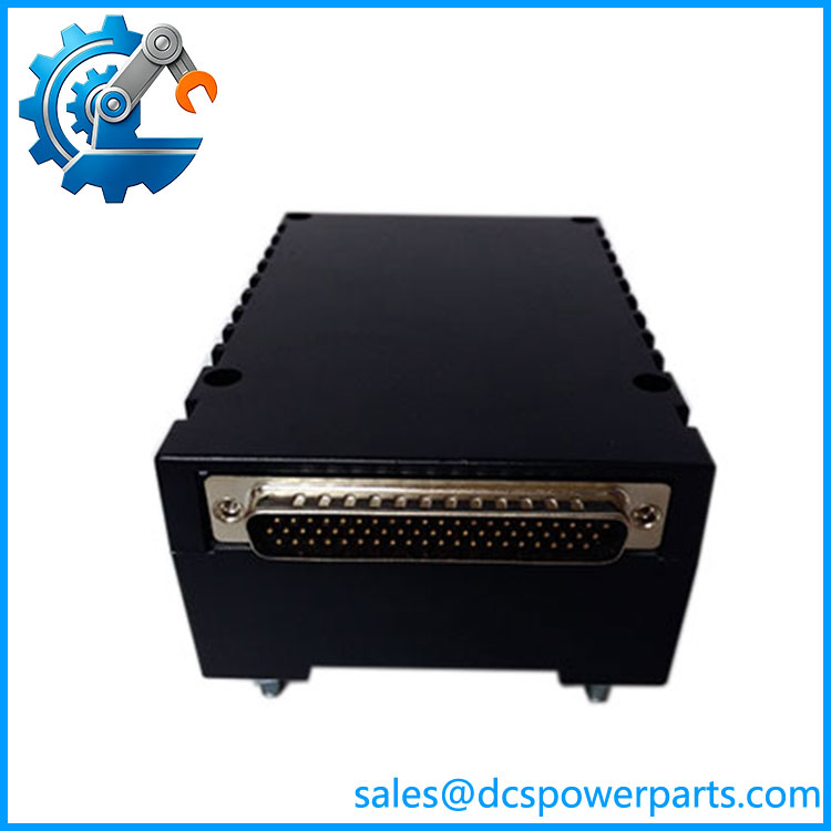
IS220PSVOH1A
2. Steam Turbine Valve Control
Steam admission and governing valves can require the same type of closed-loop position architecture. The PSVO provides the interface between the Mark VIe control network and the servo terminal/driver hardware.
3. LVDT-Based Actuator Feedback
The PSVO architecture incorporates LVDT excitation and feedback processing. That means the module is directly involved in determining actuator position rather than simply issuing an open-loop current command. GE documentation specifies the LVDT electrical interface and excitation source.
4. Fuel-Flow Pulse Measurement
The PSVO also processes two pulse-rate inputs associated with fuel-flow measurement in the Mark VIe servo architecture. This is another reason it should not be categorized as a simple servo amplifier or analog output card.
Related Products
- IS200TSVCH2A — TSVO servo terminal board associated with the .
- IS210WSVOH1A — WSVO servo driver board used with the PSVO architecture.
- IS220PSVOH1B — Related PSVO hardware revision; verify revision compatibility rather than assuming it is an automatic replacement.
- IS220PDOAH1A — Mark VIe discrete output I/O pack; different function and terminal-board architecture.
- IS220PAICH1A — Mark VIe analog I/O pack; not a substitute for PSVO servo control.
- IS220PDIAH1A — Mark VIe discrete input I/O pack.
- IS220PCLAH1A — Mark VIe core analog I/O pack.
- IS220PVIBH1A — Mark VIe vibration monitoring I/O pack.
- IS420UCSBH1A — Mark VIe controller used elsewhere in the turbine control architecture.
GE’s certification explicitly associates with IS200TSVCH2A and IS210WSVOH1A. That relationship is more important for replacement planning than superficial similarities between IS220 I/O packs.
Engineer’s Guide — Field Pitfalls to Avoid
1. Do not treat as a normal analog output card
The PSVO is responsible for a servo-control function involving valve drive, LVDT excitation, feedback acquisition, and pulse-rate inputs. Replacing it with a general-purpose AO module changes the control architecture.
2. Match the terminal board
GE identifies IS200TSVCH2A as the associated terminal board and IS210WSVOH1A as the associated servo driver. A PSVO pack should not be evaluated independently of those components.
3. Verify the hardware revision
exists with documented revisions such as Rev C, E, F, and G in service records. The revision can matter when matching the installed Mark VIe hardware and software environment. Do not assume an H1A suffix alone establishes complete compatibility.
4. Do not use an unverified ±100 mA specification as the design basis
Some secondary listings describe ±100 mA output, while GE certification gives a 120 mA maximum servo-valve output and GEH-6721D-derived records describe selectable ranges up to 120 mA. For engineering work, use the applicable GE manual and the configured servo-driver/terminal-board combination rather than relying on a reseller’s simplified output figure.
5. Check the 28 VDC supply architecture
GE’s certification specifies a 28 VDC supply for the PSVO. This is not the same as assuming a generic 24 VDC I/O pack supply. The terminal-board power arrangement should be verified before energizing a replacement.
6. Reconfiguration is part of replacement
The PSVO is configured within the Mark VIe control environment. Service records indicate that an I/O pack can be automatically reconfigured after replacement when the relevant ToolboxST configuration permits it; terminal-board changes require their own configuration checks. After replacement, the actuator should be functionally tested rather than assuming that communication alone proves correct servo operation.
7. Treat servo testing as a turbine-control activity
A PSVO replacement can affect a final control element. Valve stroking, position ramping, step-current testing, and trend verification should be performed under the site’s approved turbine maintenance procedure. This is not a module where a simple power-up and Ethernet ping constitutes a complete acceptance test.
FAQ
What is GE ?
is a PSVO Servo Control I/O Pack for the GE Mark VIe turbine control system. It interfaces I/O Ethernet networks with the TSVO servo terminal board and works with the WSVO servo driver to control two servo-valve position loops.
What terminal board is compatible with ?
GE documentation identifies as the associated terminal board. The PSVO assembly also uses the servo driver board. These components should be matched as an installed system.
What voltage does use?
GE certification specifies a 28 VDC nominal supply for the PSVO. The same documentation specifies a maximum input current of 1.0 A for the identified PSVO assembly.
How many servo valves can control?
The PSVO architecture manages two servo-valve position loops through the WSVO servo driver. It should not be confused with a two-channel generic analog-output module because the servo loops also involve position feedback and dedicated excitation circuitry.
Does support LVDT feedback?
Yes. GE documentation specifies LVDT input and excitation characteristics, and GEH-6721D-derived technical documentation describes support for multiple LVDT feedback signals. The exact field wiring should be checked against the installed TSVO terminal-board configuration.
Is the same as IS220PSVOH1B?
They are related PSVO variants, but they should not be assumed interchangeable solely from the common PSVO designation. GE documentation separately identifies the H1A and H1B variants, and the terminal-board arrangement and system revision should be checked before substitution.
What should procurement verify before buying ?
Match the complete part number and hardware revision, then verify the associated terminal board, servo driver, 28 VDC power architecture, field LVDT wiring, servo-valve current configuration, and Mark VIe software configuration. For a used spare, inspect the DC-62 connector, Ethernet ports, enclosure, LEDs, and evidence of previous thermal or field damage before installation.