Description
Product Overview
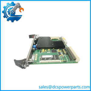
When a Series 90-70 PLC installation needs additional I/O racks, the challenge is extending the controller’s parallel bus while maintaining the original rack architecture and communication path. The GE Fanuc IC697BEM713 serves as the Bus Transmitter Module for this purpose. It sends I/O bus signals over a dedicated cable to a Bus Receiver Module in an expansion rack, allowing a compatible system to distribute PLC I/O and related modules beyond the main rack. It also provides a parallel connection for a programming device.
The GE Fanuc IC697BEM713 also has a role in supported Series 90-70 hot-standby redundancy systems, where a Bus Transmitter Module is installed in each controller’s CPU rack and connected through the Redundancy Communications Module. This makes exact model verification important: the module is not a general-purpose Ethernet switch or a standalone remote I/O controller. Before replacement, check the expansion-rack layout, cable route and length, Bus Receiver Module catalog numbers, rack slot restrictions, and whether the module is being used for I/O expansion or redundancy communications.
Key Technical Specifications
| Parameter | Specification |
|---|---|
| Product Model | IC697BEM713 |
| Manufacturer | GE Fanuc Automation |
| Product Series | Series 90-70 |
| Module Type | Bus Transmitter Module |
| Supply Voltage | 5 VDC from PLC backplane |
| Current Draw | 1.4 A |
| Effective Data Rate | 500 KB/s |
| Programmer Interface | High-speed parallel interface |
| Expansion Interface | High-speed parallel bus connection |
| Maximum Interconnecting Cable Length | 50 ft (15 m), subject to system configuration |
| Expansion Rack Support | Up to seven compatible IC697BEM711 Bus Receiver Modules |
| Status Indicators | Module OK, Programmer Port Enabled, Expansion Port Enabled |
| Mounting | One slot in the main CPU rack |
| Slot Restriction | Do not install in slot 1; follow the applicable rack and interrupt-module placement rules |
| Electrical Isolation | Non-isolated differential communication |
| Program Storage Time Reference | Approximately 20–30 seconds for a 16 KB program |
| Operating Temperature | Verify against the applicable Series 90-70 installation manual and module revision |
| Protection Rating | No separate IP rating verified for this module |
Specifications are drawn from Series 90-70 documentation and published module data. Confirm the system-specific cable arrangement and rack configuration before installation.
Major Features and Advantages
High-speed parallel bus transmission
The IC697BEM713 transfers bus signals from the main PLC rack to compatible expansion-rack hardware. Its documented effective data rate is 500 KB/s. This connection is a dedicated parallel bus interface, not an Ethernet or serial fieldbus connection.
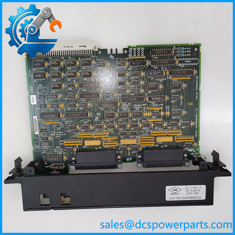
IC697BEM713
Expansion for additional I/O racks
When paired with compatible IC697BEM711 Bus Receiver Modules, the transmitter supports expansion beyond the main rack. The documented configuration supports up to seven receiver modules, with cable lengths and topology governed by the system design. Confirm each rack’s addressing and termination requirements before extending the bus.
Parallel programming connection
A separate parallel interface connects to a supported programming device. Published data lists an effective programmer-interface rate of 500 KB/s and a reference time of 20–30 seconds to store a 16 KB program. Actual transfer time depends on the system and programming setup.
Front-panel diagnostic indicators
Three LEDs help technicians check module status, programming activity, and expansion-bus communication. These indicators provide a starting point for troubleshooting but do not independently prove that every I/O point or expansion rack is operating correctly.
Support for legacy redundancy configurations
In supported Series 90-70 hot-standby systems, the IC697BEM713 connects to the Redundancy Communications Module and forms part of the communication path between primary and secondary PLC systems. This use requires the specified redundancy hardware and configuration; it should not be inferred from the module’s presence alone.
Application Scenarios and Common Pain Points
- Series 90-70 I/O expansion: Connects the CPU rack to expansion racks where additional modules are needed.
- Legacy machine-control systems: Maintains an existing parallel bus architecture when the original rack design is retained.
- Hot-standby PLC systems: Provides a communication path in documented redundancy configurations.
- Programming access: Supplies a parallel interface for supported programming equipment.
Common field issues include a missing expansion rack, incorrect cable connections, rack-address conflicts, improper termination, or a module installed in an unsuitable slot. When the expansion-bus LED is off, check the cable and receiver modules as well as the transmitter. If programming access fails, verify the programmer connection and software setup before replacing the module.
Related Products
| Model | Function |
|---|---|
| IC697BEM711 | Bus Receiver Module for Series 90-70 expansion racks |
| IC697RCM711 | Redundancy Communications Module for supported hot-standby systems |
| IC697CPU780 | CPU for Series 90-70 hot-standby redundancy applications |
| IC697CGR772 | Redundancy CPU module |
| IC697BEM731 | Genius I/O Bus Controller |
| IC697BEM733 | Genius I/O Remote I/O Scanner |
| IC697CMM742 | Ethernet interface module |
| IC697ACC702 | Terminator plug used in applicable expansion configurations |
| IC600WD005A | 5 ft expansion cable |
| IC600WD050A | 50 ft expansion cable |
These components serve different roles within the broader Series 90-70 system. Check the hardware manual before treating any item as a substitute or compatible accessory.
Engineer’s Guide: Three Checks Before Ordering
1. Confirm the intended function. Determine whether the module is used for expansion-rack communication, programming access, or a supported redundancy configuration. These uses affect the required connections and surrounding hardware.
2. Check rack placement and cabling. Verify the installation slot, cable type and length, receiver-module chain, rack addressing, and termination. Never install or remove the module with the rack powered. Follow the applicable GE Fanuc installation procedure.
3. Request condition and test evidence. For new-old-stock, refurbished, or repaired units, confirm the exact catalog number and revision, inspection results, and functional-test scope. Where practical, request evidence of programmer-port and expansion-bus operation.
Frequently Asked Questions
What is the GE Fanuc IC697BEM713 used for?
It is a Bus Transmitter Module for the Series 90-70 PLC family. Its primary role is to transmit parallel bus signals to compatible expansion racks through Bus Receiver Modules.
How many expansion racks can the support?
Published system information specifies support for up to seven compatible IC697BEM711 receiver modules. The actual configuration must follow the applicable cable-length, rack, and system restrictions.
What is the power requirement for the ?
Published specifications list a 5 VDC backplane supply and a current draw of approximately 1.4 A. Check available rack power capacity before installation.
Can the be used as an Ethernet communication module?
No. It is a parallel bus transmitter. Ethernet communication in the Series 90-70 family is handled by a suitable Ethernet interface, such as the IC697CMM742, where supported by the system.
Is the interchangeable with the IC697BEM711?
No. The is the transmitter, while the IC697BEM711 is the receiver used in expansion racks. They perform complementary functions and are not direct substitutes.
What should be checked if an expansion rack is not communicating?
Inspect the expansion cable, connector seating, receiver-module status, rack configuration, termination, and transmitter LED indications. Check the applicable manual before changing wiring or replacing components.
What information should be confirmed before purchasing a replacement?
Verify the full catalog number and revision, intended application, physical condition, rack compatibility, cable requirements, test evidence, warranty terms, and expected dispatch lead time. For a production-critical system, confirm the replacement’s functional status before scheduling the change.
Procurement recommendation: Treat the as a system-specific legacy component. Matching the model number is necessary, but confirming the rack layout, cable configuration, and functional test results is equally important.