Description
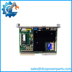
GE Fanuc IC687RCM711 | Redundancy Communications Module | Series 90-70 Hot Standby
Key Technical Specifications
| Parameter | Specification |
|---|---|
| Product | IC687RCM711 |
| Product Type | Redundancy Communications Module |
| PLC Family | GE Fanuc Series 90-70 |
| Application | Hot Standby / CPU redundancy |
| Rack Type | Dual redundant rack |
| Module Width | Half-slot VME |
| Backplane Supply | 5 VDC |
| Current Consumption | 1.2 A from 5 V bus |
| Effective Data Rate | 500 Kbytes/sec |
| Communication Type | Non-isolated differential |
| Maximum Cable Length | 50 ft / 15 m |
| VME Standard | VME C.1 |
| RCM Quantity | One RCM in each redundant CPU section |
| Manual Role Switch | Pushbutton provided |
| Status Indicators | Five LEDs |
| Configuration | Logicmaster / Windows programming configuration |
The original GE documentation specifically identifies IC687RCM711 as the RCM intended for dual redundant racks, while IC697RCM711 is intended for standard Series 90-70 racks. The RCM provides the communication path between the primary and secondary CPUs for synchronization and shared I/O transfer.
Product Introduction
The GE Fanuc IC687RCM711 is a Redundancy Communications Module used in Series 90-70 Hot Standby CPU redundancy systems. Installed in the redundant rack architecture, it provides the communication path required to synchronize the primary and backup CPUs and transfer shared I/O information between the two control units.
This is a half-slot VME module specifically associated with the dual redundant rack architecture. The module includes a manual unit-select pushbutton and five status indicators used to monitor board and redundancy-system conditions. The documented electrical interface uses the 5 V backplane and a non-isolated differential communication link.
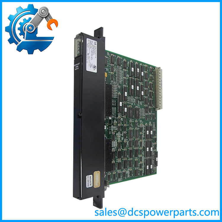
IC687RCM711
Application Scenarios & Field Pitfalls — Engineer’s Perspective
Engineering Pain Point
The IC687RCM711 is easy to misidentify because Series 90-70 contains several communication and bus-interface modules with similar catalog-number formats. It should not be treated as a general-purpose network interface or Genius remote I/O scanner.
Its actual job is tied to CPU redundancy: keeping the primary and backup controllers synchronized and providing the path for shared I/O data transfer.
Typical Applications
- Series 90-70 Enhanced Hot Standby CPU redundancy
- Dual-section redundant racks using the IC697CHS770 or IC697CHS771 architecture
- FIP redundant control systems using compatible redundancy CPUs
- Systems requiring online transfer of control responsibility between primary and backup CPUs
- Legacy process-control installations where CPU availability is critical
Technical Pitfalls to Avoid
- Do not substitute IC697RCM711 solely because the function appears identical.
GE documentation distinguishes the two by rack architecture: IC697RCM711 is for standard Series 90-70 racks, while IC687RCM711 is the half-slot RCM intended for dual redundant racks. - Check the RCM-to-BTM connection before powering the rack.
In a redundant rack, the RCM communicates through the Bus Transmitter Module. The documented architecture uses the RCM in each redundant section and the appropriate interconnecting cable. - Do not confuse the redundancy link with a normal PLC network.
The documented effective data rate is 500 Kbytes/sec, with non-isolated differential communication and a maximum cable length of 50 ft for the expansion interface. This is a dedicated redundancy-system path rather than an Ethernet or Genius network interface. - Verify the CPU and rack generation.
The Enhanced Hot Standby architecture documented by GE uses redundancy CPUs such as IC697CGR772 or IC697CGR935 and requires the appropriate rack/module arrangement.
Related Products
- IC697RCM711 — Standard Series 90-70 rack version of the Redundancy Communications Module; the principal functional counterpart, but not automatically interchangeable with .
- IC687BEM713 — Half-slot Bus Transmitter Module used with redundant rack configurations and associated redundancy communications.
- IC697BEM713 — Standard Series 90-70 Bus Transmitter Module.
- IC697CHS770 — Rear-mount dual redundant Series 90-70 rack supporting the redundant architecture.
- IC697CHS771 — Front-mount version of the dual redundant Series 90-70 rack.
- IC697CGR772 — Enhanced redundancy CPU used in Series 90-70 Hot Standby systems.
- IC697CGR935 — Enhanced redundancy CPU for the same general redundancy architecture.
- IC697CBL803 — Short I/O/redundancy cable with built-in termination used in applicable redundant rack configurations.
- IC697CBL811 — Series 90-70 I/O/redundancy interconnection cable.
- IC697CBL826 — Additional cable option associated with Series 90-70 redundancy configurations.
Procurement Check
For a replacement, verify , the rack type, CPU catalog number, BTM configuration, cable arrangement, and module revision together. The module number alone is not enough to establish interchangeability.
A particularly important check is whether the existing installation uses the dual redundant rack architecture. GE’s documentation explicitly separates from IC697RCM711 on this basis.
The original technical specification identifies 1.2 A from the 5 V bus, 500 Kbytes/sec effective data rate, 50 ft maximum cable length, non-isolated differential communication, and VME C.1 support. These are useful acceptance checks when inspecting an incoming replacement.