Description
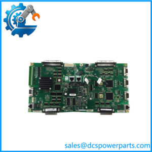
The GE DS200TCQCG1BJF is a Mark V Analog I/O Expander Board, with the functional acronym TCQC. GE Mark V documentation and technical records also refer to the TCQC function as an RST Overflow Board. For catalog purposes, “Analog I/O Expander Board” is the clearer primary classification, while RST Overflow Board can be retained as an alternate system description.
The exact GE DS200TCQCG1BJF carries 24 jumpers, three 40-pin connectors, three 34-pin connectors, and one 16-pin connector. The documented revision combination is B/J/F: first functional revision B, second functional revision J, and artwork revision F. The board also contains soldered relays used to switch circuits.
This board should not be confused with the TCQA primary analog I/O board or the TBQC/TBQB termination boards. The TCQC is an expansion/interface board within the larger Mark V analog I/O architecture. Exact connector population, jumper configuration, and the associated R/S/T core should be verified before replacement.
Technical Specifications
| Parameter | Specification |
|---|---|
| Model | DS200TCQCG1BJF |
| Manufacturer | General Electric |
| Series | Mark V / DS200 |
| Functional Acronym | TCQC |
| Product Type | Analog I/O Expander Board |
| Alternate System Description | RST Overflow Board |
| First Functional Revision | B |
| Second Functional Revision | J |
| Artwork Revision | F |
| PCB Coating | Normal coating |
| Jumpers | 24 |
| 40-Pin Connectors | 3 |
| 34-Pin Connectors | 3 |
| 16-Pin Connector | 1 |
| Relay Devices | Multiple soldered relays |
| Communication | Mark V internal board/cable architecture; no standalone Ethernet function established |
| Working Voltage | System-dependent; verify cabinet documentation |
| Operating Temperature | Not reliably established for bare PCB |
| Protection Rating | Not independently established |
| Operating Accuracy | System/configuration dependent |
The connector and revision information is supported directly by exact-model technical records.
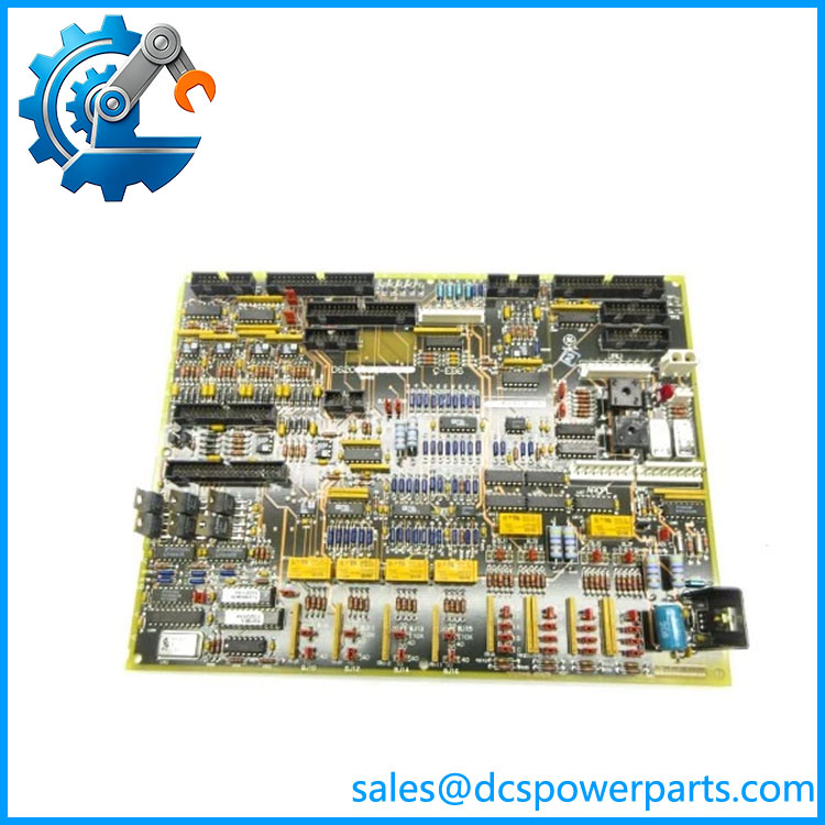
DS200TCQCG1BJF
Main Features and Engineering Considerations
The DS200TCQCG1BJF provides additional analog I/O capability within the Mark V RST architecture. Its combination of 24 jumpers and several connector types makes it a configuration-sensitive board rather than a simple plug-in terminal assembly.
The board’s three 40-pin, three 34-pin, and one 16-pin interfaces connect it to other Mark V boards and system components through ribbon-cable assemblies. Cable routing and connector identification therefore matter during maintenance. Secondary technical records specifically caution against routing these signal cables in parallel with high-power wiring because of potential interference.
The 24 jumpers are another major field concern. Their positions should be documented before replacement and matched against the site-specific configuration. A board with the same base model but a different revision or jumper arrangement should not be assumed to provide identical system behavior.
The TCQC’s “RST Overflow Board” terminology can also cause procurement confusion. It does not mean the board is a generic overflow card unrelated to analog I/O. The stronger technical records identify it as the Mark V Analog I/O Expander Board, with RST Overflow Board used as an alternate description.
Engineer’s Guide: Field Pitfalls
- Verify all 24 jumper positions before removal.
- Match B/J/F revision information.
- Check every 40-pin, 34-pin, and 16-pin connector.
- Confirm the correct R/S/T core and slot.
- Distinguish TCQC from TCQA.
- Do not apply TBQC termination-board specifications to TCQC.
- Inspect soldered relays and connector joints on refurbished boards.
- Keep ribbon-cable routing consistent with the original cabinet arrangement.
Procurement Note
For DS200TCQCG1BJF, exact revision matching is important. Request photographs of the board label, revision markings, jumper positions, connector population, and relay areas. For critical turbine applications, functional testing should cover the intended analog expansion circuits and the associated Mark V core configuration before installation.