Description
GE DS200TCQAG1BGE
Product Introduction
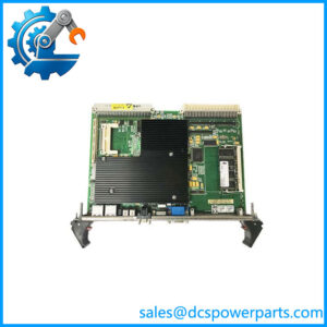
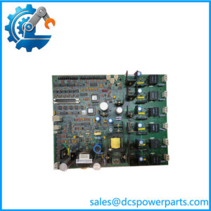
GE DS200TCQAG1BGE is a TCQA Analog Input/Output Board used in the legacy GE Mark V Speedtronic turbine control platform. The TCQA is the main analog-processing board for the R, S, and T control cores, where it receives signals from associated terminal boards and scales or conditions them for the Mark V control system. The supported signal architecture is broad: documented TCQA functions include 4–20 mA inputs and outputs, thermocouple inputs, LVDT/LVDR position signals, vibration inputs, pulse-rate signals, voltage measurements, relay-driver-related signals, and generator and line measurements.
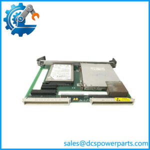
The GE DS200TCQAG1BGE is identified as a normal-coated TCQA board with first functional revision B, second functional revision G, and artwork revision E. The physical assembly contains four 34-pin connectors, two 40-pin connectors, six jumpers, and six LEDs. Ribbon-cable connections provide the signal paths between the TCQA and other Mark V boards and terminal assemblies. The board is therefore not a simple universal analog input card; its actual channel assignment depends on the Mark V cabinet design and the terminal boards connected to it.
For replacement procurement, GE DS200TCQAG1BGE should be matched by its complete identifier and revision configuration. The shorter DS200TCQAG1B identifies the same general TCQA family, but the BGE suffix provides additional revision information that should be preserved when ordering a spare. Mark V control cores also depend on consistent hardware configuration across the R, S, and T channels, so replacing one board without checking the corresponding cores can create unnecessary troubleshooting work.
Technical Specifications
| Specification | Details |
|---|---|
| Manufacturer | General Electric |
| Model | DS200TCQAG1BGE |
| Functional Acronym | TCQA |
| Product Type | Analog Input/Output Board |
| Product Family | GE Mark V DS200 |
| Control System | Mark V Speedtronic |
| Functional Revision | B |
| Secondary Functional Revision | G |
| Artwork Revision | E |
| PCB Coating | Normal coating |
| Main Function | Analog signal scaling and conditioning |
| 4–20 mA Inputs | Supported |
| 4–20 mA Outputs | Supported |
| Thermocouple Inputs | Supported |
| LVDT/LVDR Inputs | Supported |
| Vibration Inputs | Supported |
| Pulse-Rate Inputs | Supported |
| Voltage Inputs | Supported |
| Generator/Line Signals | Supported |
| 34-Pin Connectors | 4 |
| 40-Pin Connectors | 2 |
| Hardware Jumpers | 6 |
| Diagnostic LEDs | 6 |
| Internal Processing | Analog processing and Mark V interface circuitry |
| System Architecture | R/S/T control cores |
| Communication | Internal Mark V board-to-board interfaces |
| Standalone Ethernet | Not established |
| Standalone IP Rating | Not applicable |
| Measurement Accuracy | Application-dependent; no single board-level accuracy value established |
The exact board documentation supports the connector, jumper, LED, revision, and signal-function information above. A universal input voltage, output current, operating temperature, or accuracy figure should not be assigned to this board without the applicable Mark V hardware manual and application configuration.
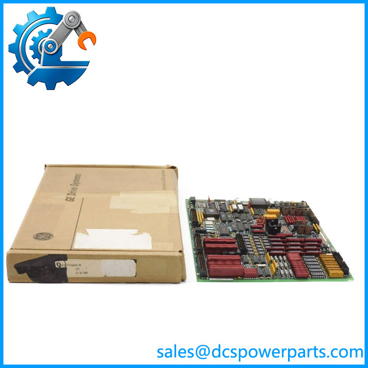
DS200TCQAG1BGE
Main Features and Engineering Considerations
Broad analog signal processing
The main role of the DS200TCQAG1BGE is to scale and condition analog information arriving from Mark V terminal boards. This includes 4–20 mA process signals, thermocouples, LVDT/LVDR position signals, vibration measurements, pulse-rate inputs, and generator/line measurements. That mixed-signal architecture is why the TCQA should not be treated like a modern PLC card with a fixed number of identical analog channels.
4–20 mA interface
The TCQA contains dedicated circuitry for 4–20 mA input and output functions. Records associate these signals with the JB interface and TBQC terminal-board architecture. Fuel-flow pressure and compressor stall-detection signals are examples of 4–20 mA inputs that can be scaled and conditioned by the TCQA. Actual signal allocation remains application-specific.
Thermocouple and temperature signals
Thermocouple signals form another part of the TCQA architecture. This does not mean that every TCQA installation has the same thermocouple channel population. The Mark V I/O configuration and associated terminal boards determine which physical inputs are assigned to temperature measurement.
LVDT/LVDR and vibration interfaces
The TCQA also participates in turbine position and vibration measurement. LVDT/LVDR signals use dedicated interface circuitry, while vibration signals arrive through the appropriate terminal-board connection. These circuits should be checked against the turbine-specific drawings before troubleshooting a failed measurement.
Pulse-rate processing
The TCQA contains pulse-rate input circuitry used with turbine speed-related signals. Records identify pulse-rate signals associated with magnetic pickup and TTL-type sources and describe their use in turbine fuel and speed-control applications. This is another reason that the board cannot be reduced to a generic “analog input” classification.
R/S/T control-core architecture
The Mark V uses R, S, and T control cores as part of its redundant control architecture. Current technical descriptions identify the TCQA as the principal analog I/O card in each of these cores. For a replacement, compare the failed board against the corresponding cards in the other cores. Differences in revision, jumper configuration, or connector population can be useful diagnostic clues.
Revision-specific procurement
The requested identifier ends in BGE, while other TCQA boards may carry different revision tails. The exact suffix should remain on the purchase order. Do not assume that a visually similar TCQA board is an automatic substitute solely because its basic DS200TCQAG1B portion matches.
Application Scenarios
Gas Turbine Control
The TCQA board is used within Mark V gas-turbine control systems to process analog instrumentation associated with turbine operation and protection.
Steam Turbine Control
Mark V steam-turbine installations can use the same TCQA architecture for process, position, temperature, vibration, and electrical measurements.
Fuel and Process Measurement
4–20 mA signals such as fuel-flow pressure and compressor-related measurements can be scaled and conditioned through the TCQA signal chain.
Turbine Position Monitoring
LVDT/LVDR inputs provide position feedback used by turbine control functions. The TCQA provides the associated signal-processing path.
Generator and Line Measurement
Generator and line signals are part of the broader TCQA/TCQC analog architecture, allowing electrical measurements to participate in Mark V control and monitoring functions.
Engineer’s Guide: Field Pitfalls
1. Do not call it a simple 4–20 mA card.
The TCQA handles several different signal types. Its application is defined by the terminal-board wiring and Mark V configuration.
2. Match the complete part number.
contains revision information beyond the basic TCQA identifier. Preserve the entire suffix when sourcing a replacement.
3. Check the R/S/T core counterparts.
If the system is operating normally on two cores, compare the failed board’s revision, jumper positions, LED behavior, and connector population with the other cores.
4. Verify the terminal-board chain.
A failed field measurement does not automatically mean the TCQA has failed. Check the applicable TBQC, TBQB, TCQC, or other terminal/interface board first.
5. Do not pull ribbon cables by the cable itself.
The board uses multiple ribbon-cable connections. Connector and cable damage can create intermittent faults that are difficult to distinguish from PCB problems.
6. Record jumper settings.
The board contains six jumpers. Photograph the original configuration before removal and compare it with the replacement.
7. Do not assume a universal 24 VDC specification.
Some secondary product listings publish 24 VDC and 1 A figures for the TCQA family, but those figures are not sufficiently controlled to represent every board-level operating condition. Use the Mark V cabinet drawings for power requirements.
8. Test the actual signal path.
After replacement, verify the relevant analog channels using known signal sources or appropriate simulator equipment. Check scaling at the operator interface rather than relying only on LED status.
9. Check the artwork revision.
The requested board is revision E at the artwork level. A different artwork revision should be reviewed before substitution.
Frequently Asked Questions
What is GE ?
It is a GE Mark V TCQA Analog Input/Output Board used to scale and condition multiple analog signal types within the Mark V turbine-control architecture.
What does TCQA stand for?
TCQA is the functional acronym used for the Mark V analog I/O board. The board is commonly described as the RST/TC2000 analog I/O board in Mark V documentation and equipment records.
What signal types can the TCQA handle?
The documented architecture includes 4–20 mA inputs and outputs, thermocouple signals, LVDT/LVDR position signals, vibration inputs, pulse-rate signals, voltage inputs, and generator/line signals.
How many connectors does have?
The documented assembly contains four 34-pin connectors and two 40-pin connectors.
How many jumpers are on the board?
The board is documented with six hardware jumpers. The actual settings should be compared against the original board and the Mark V application documentation before installation.
Does have Ethernet?
No standalone Ethernet interface is established for this board. It operates within the Mark V internal control architecture through its board-to-board and terminal-board connections.
Is the same as DS200TCQAG1B?
They belong to the same TCQA functional family, but the complete BGE identifier contains additional revision information. For procurement, the complete number should be matched rather than assuming all TCQA revisions are interchangeable.
Is the board used in Mark VI?
The controlled identification for is GE Mark V DS200. Do not use Mark VI/Mark VIe terminology from generic reseller pages to determine compatibility.
What should be checked before purchasing a replacement?
Verify the complete part number, functional and artwork revisions, jumper positions, connector population, R/S/T core location, associated terminal boards, and the actual Mark V I/O configuration.
Procurement Note
For a replacement order, specify GE — TCQA Analog Input/Output Board exactly as marked on the PCB. For used or refurbished hardware, request photographs showing the full board label, revision markings, PROM/IC population, connectors, jumpers, and PCB condition.
The important engineering point is that this is a multi-function Mark V analog processing board, not a generic PLC analog module. The six jumpers, multiple connector groups, and mixed signal circuitry make configuration matching important. Before approving a substitute, compare the BGE board against the installed R/S/T-core cards and the turbine’s I/O configuration documentation.