Description
GE DS200TBQCG1AAA RST Analog Termination Board
Product Introduction
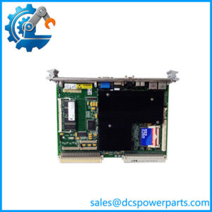
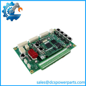
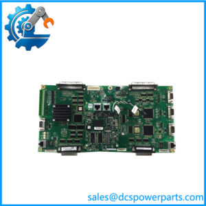
The GE DS200TBQCG1AAA is a TBQC RST Analog Termination Board used in the GE Mark V turbine control architecture. Its primary role is signal termination and routing between field circuits and the associated TCQA analog I/O hardware. This is an important distinction: the TBQC is not the primary analog-processing board. It provides the physical interface through which milliamp and LVDT/R-related signals are connected to the Mark V control core. Technical records identify the board as an Analog Input Milliamp Input/Output Termination Module and also as an RST Analog Termination Board.
The GE DS200TBQCG1AAA contains two terminal blocks with 83 signal-wire terminals each, together with 15 hardware jumpers and three 40-pin plus three 34-pin connectors. Five principal connector interfaces are documented: JBR, JFR, JBS/T, JFS/T, and TEST. JBR is associated with TCQA board input/output signals, while JFR handles LVDT/R position signals. JBS/T and JFS/T are associated with Mark V R/S/T architecture, while TEST is primarily relevant to service and factory testing.
For replacement work, the GE DS200TBQCG1AAA should be matched by the complete part number and installed configuration. The 15 jumpers are particularly important because some configure milliamp inputs and some are intended for factory or test functions. Before replacing an installed board, record jumper positions, connector population, terminal assignments, and the associated TCQA board configuration. Do not treat another TBQC variant as automatically interchangeable.
Technical Specifications
| Parameter | Specification |
|---|---|
| Product Model | DS200TBQCG1AAA |
| Manufacturer | General Electric (GE) |
| Product Series | Mark V / DS200 Speedtronic |
| Functional Acronym | TBQC |
| Product Type | RST Analog Termination Board |
| Functional Description | Analog Input Milliamp Input/Output Termination Module |
| Primary Function | Analog signal termination and routing |
| Associated Analog Board | TCQA |
| Terminal Blocks | 2 |
| Signal Terminals | 83 per terminal block |
| Hardware Jumpers | 15 |
| 40-Pin Connectors | 3 |
| 34-Pin Connectors | 3 |
| Principal Connections | JBR, JFR, JBS/T, JFS/T, TEST |
| JBR | TCQA board input/output signal interface |
| JFR | TCQA LVDT/R position signal interface |
| Typical Input Signals | 4–20 mA and LVDT/R position signals |
| Documented Output Range | 20–200 mA, depending on configured circuit |
| Instruction Manual | GEH-6153 |
| Communication Protocol | No standalone Ethernet/fieldbus function |
| Operating Accuracy | Not a standalone measurement module; system accuracy depends on the complete Mark V signal chain |
| Operating Temperature | Not reliably established for the bare board |
| Protection Rating | Not independently established |
| Mounting | GE Mark V control-core / terminal-board assembly |
The 4–20 mA input and 20–200 mA output information is documented for this exact board family, while exact circuit assignments depend on the Mark V configuration.
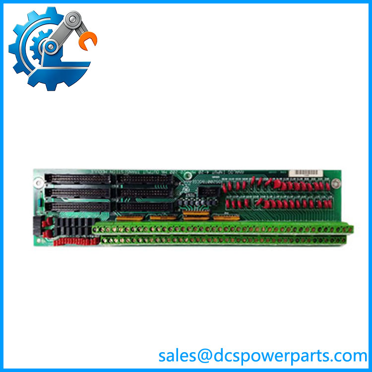
DS200TBQCG1AAA
Main Features and Engineering Considerations
Dedicated Analog Termination Function
The DS200TBQCG1AAA is best understood as an interface board. The actual analog processing is performed elsewhere in the Mark V architecture, particularly through the associated TCQA circuitry. Calling the TBQC itself an independent analog input module can create confusion during troubleshooting because a field signal problem may originate from the termination board, wiring, TCQA board, or the connected sensor.
4–20 mA and LVDT/R Interfaces
The board handles milliamp signal paths and LVDT/R position signals. The JBR interface connects to TCQA analog circuitry, while JFR is specifically associated with LVDT/R position signals. This makes the board relevant to turbine-control measurements where both conventional current-loop signals and position feedback are part of the Mark V architecture.
Fifteen Hardware Jumpers
The 15 jumpers are one of the most important field-service considerations. Technical documentation identifies BJ1 through BJ15 as being associated with milliamp input configuration, including connections to DCOM. Some jumper positions are intended for factory testing rather than normal field adjustment. A replacement board should therefore be configured to match the removed board unless the engineering documentation specifies a different arrangement.
High-Density Termination
Two 83-terminal blocks provide a substantial field-wiring interface. This density is useful in a turbine-control cabinet but increases the chance of wiring errors during replacement. Terminal numbering, wire tags, connector locations, and the R/S/T core assignment should be checked against the cabinet drawing before energization.
Mark V Architecture Matters
Several online listings incorrectly describe this exact part as a Mark VI board, digital I/O board, or generic PLC card. Those classifications conflict with the stronger TBQC-specific records identifying as a Mark V analog termination board.
Application Scenarios
- GE Mark V gas turbine control systems
- GE Mark V steam turbine control systems
- R/S/T turbine-control cores
- 4–20 mA analog signal termination
- LVDT/R position signal termination
- TCQA analog I/O interface
- Turbine actuator and instrumentation signal routing
- Mark V cabinet refurbishment
- Legacy turbine-control spare-parts programs
Engineer’s Guide: Field Pitfalls
1. Do not confuse TBQC with TCQA.
TBQC is the termination/interface board. TCQA is the associated analog I/O processing board. They are different components with different troubleshooting responsibilities.
2. Record all 15 jumper positions.
Do this before removing the original board. Some jumper positions affect signal configuration, while others are associated with factory/test functions.
3. Verify the R/S/T core assignment.
A Mark V turbine installation may contain multiple control cores. The physical board location and connected TCQA circuitry should be confirmed before replacement.
4. Check JBR and JFR separately.
JBR handles the TCQA analog signal interface, while JFR is associated with LVDT/R position signals. Do not assume that all connectors carry the same type of signal.
5. Do not copy generic analog specifications.
Listings claiming universal ±10 V inputs, Modbus, Profibus, or generic 0–10 V outputs are not supported by the stronger exact-model records.
6. Check the complete part number.
DS200TBQCG1, DS200TBQCG1A, , and other TBQC variants should not be treated as interchangeable without checking the engineering documentation.
7. Inspect the terminal hardware.
On a used or refurbished unit, inspect terminal screws, connector housings, jumper headers, solder joints, and signs of heat or contamination before installation.
Frequently Asked Questions
What is GE ?
It is a GE Mark V TBQC RST Analog Termination Board, with the functional description Analog Input Milliamp Input/Output Termination Module.
Is an analog input card?
It is an analog termination/interface board rather than the primary analog-processing card. It works with associated Mark V TCQA circuitry.
What signals does handle?
Documented signal types include 4–20 mA analog signals and LVDT/R position inputs. A documented output configuration uses 20–200 mA signals, with the exact circuit behavior determined by the Mark V configuration.
How many terminals are on the board?
The board has two terminal blocks with 83 signal-wire terminals per block.
How many jumpers does it have?
The exact board is documented with 15 hardware jumpers, BJ1 through BJ15.
What are the main connectors?
The principal documented connections are JBR, JFR, JBS/T, JFS/T, and TEST. JBR is associated with TCQA input/output signals, while JFR handles LVDT/R position signals.
Does use Ethernet or Modbus?
No standalone Ethernet or Modbus function has been established for this board. It is a Mark V termination/interface component rather than a network communications module.
What should be checked before ordering a replacement?
Verify the complete part number, board revision, R/S/T core location, terminal wiring, connector population, jumper positions, associated TCQA board, and the actual field signal configuration.
Procurement Note
For a critical Mark V replacement, request photographs showing the complete board label, revision markings, terminal blocks, connectors, and all 15 jumper positions. A generic “TBQC analog board” description is not enough for interchangeability.
For refurbished inventory, incoming inspection should include visual PCB inspection, terminal and connector inspection, jumper-position verification, continuity checks where appropriate, and functional testing against the intended Mark V configuration. Avoid accepting unsupported claims about universal voltage ranges, communication protocols, temperature ratings, or accuracy simply because they appear on a reseller listing.