Description
GE DS200TBCAG1AAB
Product Introduction
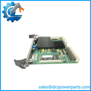
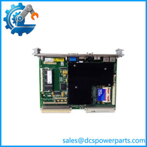
GE DS200TBCAG1AAB is an RTD analog input termination board used in the GE Mark V Speedtronic turbine control architecture. Its functional designation is TBCA, and its primary job is to provide the field termination point for RTD temperature signals before those signals are passed to the associated TCCA analog I/O board for excitation, measurement, and processing. The available Mark V documentation and equipment records identify two 50-pin connections: JCC routes RTD signals 1 through 15, while JDD routes signals 16 through 30 to the TCCA board.
The GE DS200TBCAG1AAB uses two terminal blocks containing 90 signal-wire terminals each. This high-density arrangement is consistent with the wiring requirements of a 30-channel RTD interface, where multiple conductors are required for each sensor circuit. The board itself should not be confused with the TCCA analog processing board. The TBCA provides termination and signal routing; the downstream TCCA hardware performs the actual RTD measurement and conversion functions. Available records also indicate that the TBCA has no user-configurable hardware jumpers.
For replacement work, GE DS200TBCAG1AAB should therefore be treated as a Mark V turbine-control termination component rather than a generic PLC analog-input card. The complete suffix is important because DS200TBCAG-family boards have different functions and signal arrangements. Field wiring, JCC/JDD ribbon connections, R5-core location, and the associated TCCA board should all be verified before approving a replacement. Several current online listings incorrectly mix Mark V and Mark VI/Mark VIe terminology, so the actual equipment label and GE documentation should take precedence over marketplace descriptions.
Technical Specifications
| Specification | Details |
|---|---|
| Manufacturer | General Electric (GE) |
| Model | DS200TBCAG1AAB |
| Functional Acronym | TBCA |
| Product Type | RTD / Analog Input Terminal Board |
| Product Family | Mark V DS200 |
| Control System | GE Speedtronic Mark V turbine control |
| Primary Function | RTD field termination and signal routing |
| RTD Signal Paths | 30 |
| JCC Function | Routes RTD signals 1–15 to TCCA |
| JDD Function | Routes RTD signals 16–30 to TCCA |
| Terminal Blocks | 2 |
| Signal Terminals | 90 per terminal block |
| Total Terminal Positions | 180 |
| Internal Connectors | 2 × 50-pin |
| Associated Processing Board | TCCA |
| Installation Context | R5 core / TBCA termination position |
| Hardware Jumpers | None documented |
| Firmware | None; termination board rather than processor |
| Communication Protocol | None; point-to-point/internal signal routing |
| Operating Voltage | No standalone supply rating established |
| Protection Rating | Not applicable as a standalone field enclosure |
| Measurement Accuracy | Determined by the associated RTD input/processing circuitry, not the TBCA termination board |
The 30-channel/JCC-JDD architecture and terminal arrangement are supported by multiple equipment records. The exact electrical ratings of the terminal points should not be inferred from generic PCB or Mark V cabinet ratings.
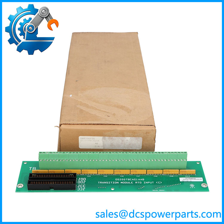
DS200TBCAG1AAB
Main Features and Engineering Considerations
30-channel RTD termination architecture
The defining feature of the DS200TBCAG1AAB is its high-density RTD termination arrangement. The documented architecture divides the 30 RTD signal paths into two groups. JCC carries channels 1–15 and JDD carries channels 16–30 to the TCCA board. This division simplifies the connection between the field termination hardware and the processing electronics in the R5 core.
Passive signal-routing role
The TBCA should not be represented as an independent temperature transmitter or RTD signal conditioner. The available technical records describe it as a termination/interface board. The associated TCCA hardware is responsible for the measurement circuitry. This distinction matters when troubleshooting a temperature channel: an open or incorrect field termination can produce a bad reading even when the TCCA itself is operating correctly.
High-density field wiring
Each RTD circuit can require several conductors, so the two 90-terminal blocks provide the physical capacity required by the 30-channel architecture. During replacement, the safest procedure is to identify every wire by its existing terminal designation before removing it. Current equipment records specifically caution against damaging the ribbon cables and recommend handling the connector body rather than pulling directly on the ribbon cable.
JCC and JDD routing
The JCC/JDD distinction is a critical commissioning detail. JCC is associated with RTD signals 1–15 and JDD with 16–30. Swapping or mis-seating these connections can move an entire group of temperature signals to incorrect processing channels. Verify the core drawing and connector labels before energization.
Legacy Mark V architecture
The belongs to the legacy GE Mark V DS200 hardware family. Some current listings describe it as Mark VI, Mark VIe, or a generic analog I/O board, but those descriptions should not be used to establish system compatibility. GE Mark V equipment records specifically identify the TBCAG1 family within the Mark V system.
Revision control
The complete identifier is : the functional revision and artwork revision form part of the identification. A visually similar DS200TBCAG, TBCBG, or TBCAG2 board should not be substituted simply because it has a similar terminal layout. Different DS200 terminal boards serve different signal types and routing schemes.
Application Scenarios
Gas Turbine Temperature Monitoring
The TBCA termination architecture is used within GE Speedtronic Mark V turbine-control systems to connect RTD temperature sensors into the controller’s analog input chain.
Turbine Bearing Temperature
RTDs associated with bearing temperature monitoring can be routed through the TBCA before processing by the TCCA board.
Winding and Auxiliary Temperature Monitoring
Generator or turbine auxiliary temperature measurements can also form part of the RTD signal set, subject to the specific turbine wiring configuration.
Exhaust and Process Temperature Monitoring
Where the Mark V application uses RTD sensors rather than thermocouples or transmitters, the TBCA provides the corresponding field termination interface.
Engineer’s Guide: Field Pitfalls
1. Do not classify it as a generic analog I/O card.
The TBCA is primarily a termination/routing board. The TCCA provides the associated RTD processing.
2. Verify the exact Mark V architecture.
The part is associated with the Mark V DS200 family. Listings that call it Mark VI or Mark VIe should not override the actual cabinet documentation.
3. Check JCC versus JDD.
JCC routes RTD channels 1–15; JDD routes channels 16–30. Verify both connections before commissioning.
4. Label every field wire before removal.
With up to 180 terminal positions, a single misplaced conductor can create a difficult temperature-channel troubleshooting problem.
5. Protect the ribbon cables.
Disconnect the connector by its housing. Do not pull on the ribbon itself.
6. Verify the associated TCCA board.
A correct TBCA replacement does not compensate for a wrong or defective TCCA configuration.
7. Do not invent RTD accuracy specifications for the TBCA.
The termination board does not establish the measurement accuracy. That depends on the downstream excitation, analog measurement, sensor type, wiring, and TCCA processing.
8. Confirm the complete suffix.
should be matched exactly. Similar-looking DS200 terminal boards can have different signal functions and connector assignments.
Frequently Asked Questions
What is GE ?
It is a GE Mark V TBCA RTD/analog input termination board used to route RTD field signals to the associated TCCA analog I/O board.
How many RTD channels does it support?
The documented TBCA architecture provides 30 RTD signal paths, divided into channels 1–15 through JCC and channels 16–30 through JDD.
What are JCC and JDD?
They are the two 50-pin internal connections used to route the RTD signal groups to the TCCA board. JCC handles signals 1–15 and JDD handles signals 16–30.
Does perform RTD-to-temperature conversion?
No. It is a termination/routing board. The associated TCCA analog I/O circuitry performs the RTD measurement and processing functions.
Does the board have hardware jumpers?
Available Mark V records indicate that the TBCA terminal board does not have hardware jumpers for user configuration.
Is a Mark VI board?
The stronger identification is GE Mark V DS200 / Speedtronic TBCA. Some reseller pages incorrectly label it Mark VI or Mark VIe, so the installed system documentation and actual board marking should be used for compatibility decisions.
What should be checked before purchasing a replacement?
Verify the complete identifier, functional/artwork revisions, Mark V core location, JCC/JDD routing, terminal numbering, associated TCCA board, and physical condition of the terminal blocks and ribbon connectors.
Procurement Note
For a replacement order, specify in full rather than ordering only a “TBCAG terminal board.” Request clear photographs of the board label, connector population, and revision markings for used or refurbished hardware.
The most important technical point is that this board is part of the RTD signal chain, not the RTD measurement electronics itself. A replacement should be checked against the R5/TCCA architecture and the actual field wiring before installation. The available documentation consistently supports the JCC/JDD 30-channel RTD routing arrangement, while generic voltage, current, accuracy, and temperature specifications published by some sellers are not sufficiently reliable to use as engineering design values.