Description
Product Overview
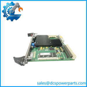
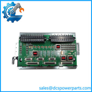
The GE DS200CTBAG1A is an analog termination board used in the SPEEDTRONIC Mark V turbine control system. Identified by the functional acronym CTBA, this printed circuit board provides an interface for analog signals and associated control-system connections. In a turbine-control cabinet, its job is to support the correct routing of signal paths between the termination layer and the relevant electronic boards. It is an interface component, not a standalone programmable controller or an independent turbine-control processor.
Within the Mark V architecture, the DS200CTBAG1A is associated with 4–20 mA analog inputs and outputs, shaft-voltage and shaft-current signal connections, and communication links used by the control system. Its documented interfaces include IONET connections associated with the STCA board and COREBUS-related connections in the Mark V control arrangement. A nine-pin RS-232 monitor port supports diagnostic access. Hardware jumpers also affect specific electrical reference connections, so the installed configuration matters during replacement. These details make the board relevant to turbine instrumentation, control-cabinet maintenance, and fault isolation when an analog signal path or board-level interface is suspected.
For maintenance teams supporting legacy gas or steam turbine installations, the GE DS200CTBAG1A can serve as a replacement candidate when an installed CTBA board fails or exhibits an interface-related fault. Correct part identification is only the starting point, however. Before installation, compare the complete board number, functional revision, connector positions, jumper configuration, and cabinet wiring against the removed assembly and applicable OEM documentation. A similar-looking board from the same DS200 family is not sufficient evidence of interchangeability.
From a procurement standpoint, the practical value of the GE DS200CTBAG1A depends on traceable identification, condition verification, and application-specific compatibility checks. For a legacy replacement, confirm whether the supplied board is unused surplus, refurbished, or previously installed and tested. That distinction affects acceptance testing, warranty expectations, and the risk of returning a turbine-control cabinet to service with an unsuitable component.
Product Introduction (Non-Templated)
An intermittent 4–20 mA signal does not automatically mean the controller has failed. Termination connections, wiring, jumper settings, and the associated I/O electronics all warrant inspection before a board is condemned.
The GE DS200CTBAG1A serves as the CTBA analog termination interface in the Mark V turbine-control ecosystem. Its analog signal paths, IONET connections, and diagnostic interface make it relevant to planned maintenance and legacy replacement projects. No verified numerical improvement in signal accuracy or processing speed should be assumed from replacing the board alone.
Key Technical Specifications
| Parameter | Value |
|---|---|
| Manufacturer | General Electric (GE) |
| Model | DS200CTBAG1A |
| Product Series | SPEEDTRONIC Mark V DS200 |
| Functional Acronym | CTBA |
| Product Type | Analog termination board |
| Primary Application | Mark V turbine-control systems |
| Analog Signal Type | 4–20 mA input and output paths |
| Communication Interfaces | IONET and COREBUS-related connections |
| Diagnostic Interface | RS-232, 9-pin D-shell |
| Associated Boards | STCA, TCCA, QTBA, TCPD and TCDA, depending on connection |
| Jumper Configuration | BJ1–BJ14 and BJ15; verify against board documentation |
| Functional Revision | Group 1, Revision A designation |
| Mounting | Mark V control-cabinet assembly; confirm physical installation |
| Operating Temperature | Confirm against applicable OEM documentation |
| Supply Voltage | Confirm from the installed system and OEM documentation |
| Power Consumption | No verified value established for this exact configuration |
| Protection Rating | No standalone IP rating verified |
| Firmware Compatibility | Not specified as a standalone firmware-controlled module |
| Condition | Must be confirmed for the individual unit |
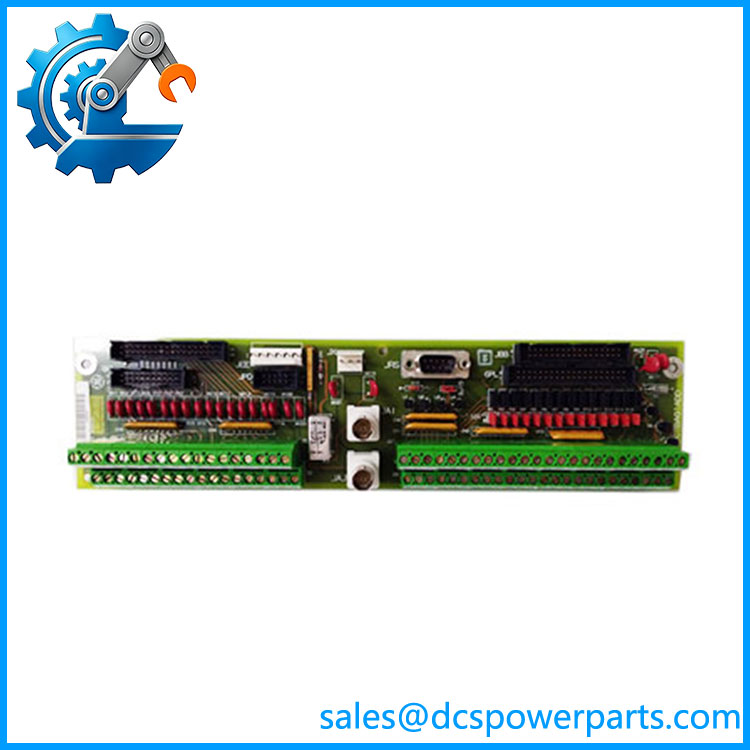
DS200CTBAG1A
Related Products
The following models are associated with the GE Mark V control-system family. They serve different interface, I/O, or power functions; compatibility must be checked against the installed cabinet and revision documentation.
DS200CTBAG1ACC
A related CTBA board designation. Consider it during legacy replacement research, but verify functional and artwork revisions, connectors, and jumper assignments before treating it as interchangeable with .
DS200CTBAG1ADD
Another CTBA variant associated with the Mark V family. It may be relevant when investigating revision alternatives, but a suffix difference requires documented compatibility confirmation.
DS200TCCAG1A
Analog I/O board used in the Mark V ecosystem. It performs a different function from the CTBA termination board and may be relevant when troubleshooting the associated analog signal-processing path.
An associated Mark V board referenced in CTBA IONET connections. Confirm the complete installed part number before ordering a replacement for any STCA assembly.
DS200TCPDG1A
Power-distribution board from the Mark V family. Relevant when investigating power-distribution connections associated with turbine-control hardware; it is not a direct substitute for an analog termination board.
DS200TCPSG1A
DC input power-supply board used in Mark V control assemblies. Consider it when troubleshooting a supply-related fault rather than an isolated analog termination issue.
DS200DTBAG1A
Digital-contact termination board for a different signal category. It may be relevant to digital input troubleshooting, but its function differs from the CTBA analog interface.
DS200PTBAG1A
Mark V P-core termination board. It belongs to the broader termination-board family but serves a different control-system position; do not substitute it based on family resemblance alone.
Frequently Asked Questions (FAQ)
1. Is the GE compatible with every Mark V turbine-control cabinet?
No blanket compatibility claim is appropriate. The board is associated with the Mark V CTBA analog termination function, but the installed core arrangement, connector assignments, functional revision, and existing wiring determine whether a particular unit is suitable.
Before ordering, verify:
- The complete part number and revision on the existing board.
- The cabinet and core location.
- The connector layout and jumper positions.
- The applicable OEM drawings and wiring documentation.
2. Can I hot-swap the while the turbine is running?
Do not assume that hot-swapping is permitted. This board participates in turbine-control signal interfaces, and removing it may interrupt signals or affect associated communications.
Use the site’s approved maintenance procedure, determine the operational consequences of losing the board, and establish the required shutdown or isolation conditions before removal. A general statement that the board is replaceable does not establish that live replacement is safe.
3. Does the support firmware v3.1?
A standalone firmware version such as v3.1 is not established for this board by the available identification information. The is an analog termination board, not a conventional software-programmed PLC CPU.
For compatibility assessment, check the Mark V system software and hardware documentation, the installed board revision, and the associated controller and I/O configuration. Do not use a firmware version alone to approve a board substitution.
4. Will replacing the erase my turbine-control logic?
The board is an interface component rather than the primary repository for turbine application logic. Replacing it should not be treated as a controller-program download or logic migration.
That does not eliminate commissioning risk. Before replacement, preserve relevant system records and document connector positions, wiring, jumper settings, and existing alarms. After installation, verify signal paths and communications under the site’s approved test procedure.
5. How can I verify that a new-surplus is genuine and unused?
The part number alone cannot prove authenticity or condition. Request evidence that relates to the actual unit being supplied.
- Inspect the complete board label, revision markings, and serial identification where present.
- Request current photographs of the actual PCB, connectors, and component side.
- Check for soldering marks, repair evidence, damaged traces, corrosion, or handling damage.
- Request documented test results where testing is offered.
- Confirm in writing whether the unit is new surplus, refurbished, or used and tested.
A factory-sealed claim should be supported by credible packaging and traceability evidence. New surplus does not automatically mean recently manufactured or factory-tested.
6. What should I check before ordering a as a legacy replacement?
The safest approach is to match the installed hardware rather than relying on a family-level description.
- Record the full part number and revision.
- Compare connector positions and associated board interfaces.
- Document jumper settings and field-wiring terminations.
- Confirm the intended cabinet position and system configuration.
- Obtain written confirmation of compatibility and the supplied unit’s condition.
For a turbine that cannot tolerate extended downtime, arrange inspection and acceptance testing before scheduling the replacement.
7. What warranty should I expect when purchasing the ?
Warranty coverage depends on the supplier’s written terms and the condition of the individual unit. New-surplus, refurbished, and used-and-tested boards may have different coverage.
Before purchase, confirm the warranty period, coverage for functional failure, return authorization requirements, and any testing or installation exclusions. For critical turbine-control spares, also clarify how a defective unit will be handled if it fails during incoming inspection or approved commissioning tests.