Description
Key Technical Specifications
| Parameter | Specification |
|---|---|
| Product Model | 7DO135.70 |
| Manufacturer | B&R Industrial Automation |
| Product Family | B&R System 2003 |
| Module Type | Digital Output Module |
| Output Channels | 4 |
| Output Technology | FET |
| Output Voltage | 12–24 VDC nominal |
| Minimum Switching Voltage | 11.4 VDC |
| Maximum Switching Voltage | 30 VDC |
| Continuous Current | 0.1 A per output |
| Maximum Module Current | 0.4 A |
| Maximum Switching Frequency | 100 kHz |
| Switching Configuration | Push/pull |
| Reverse Polarity Protection | Yes |
| Short-Circuit Protection | Yes |
| Overload Protection | Yes |
| Typical Voltage Drop | ≤0.6 V at 0.1 A |
| Maximum Capacitive Load | 20 nF |
| Short-Circuit Current | Approximately 0.11–0.3 A |
| Maximum Power Consumption | 0.2 W |
| Mounting | B&R 2003 screw-in module |
| Interface | CP interface / AF101 adapter |
| Terminal Block | TB712, ordered separately |
| Certification | C-UL-US listed in B&R documentation |
B&R’s current product information identifies the 7DO135.70 as a 2003 digital output module with four FET outputs, 12–24 VDC, 0.1 A, screw-in construction.
The older B&R technical catalog provides the more detailed electrical limits: 11.4 VDC minimum, 30 VDC maximum, 0.1 A maximum per output, 0.4 A maximum for the module, and 100 kHz maximum switching frequency.
Application Scenarios & Pain Points
A small output card can become a disproportionately large maintenance problem when the machine depends on fast pulse switching or when the original 2003 architecture is no longer actively supported. A replacement that merely provides “24 VDC digital outputs” is not necessarily electrically equivalent.
- High-speed machine control: The FET architecture and 100 kHz maximum switching frequency make the module suitable for applications requiring substantially faster switching than ordinary relay outputs.
- B&R System 2003 machinery: The module was designed for the 2003 platform and can interface through the CP interface or AF101 adapter.
- Pulse and actuator control: Four semiconductor outputs can drive appropriate low-current DC loads, provided the load stays within the 0.1 A per-output limit.
- Legacy automation maintenance: Particularly useful when an older B&R machine must remain operational without replacing the complete control cabinet.
Field note: The 0.1 A rating deserves attention. A solenoid or contactor coil that draws more current than expected can damage an output even when its nominal voltage is 24 VDC. Measure the actual load current rather than relying solely on the actuator nameplate.
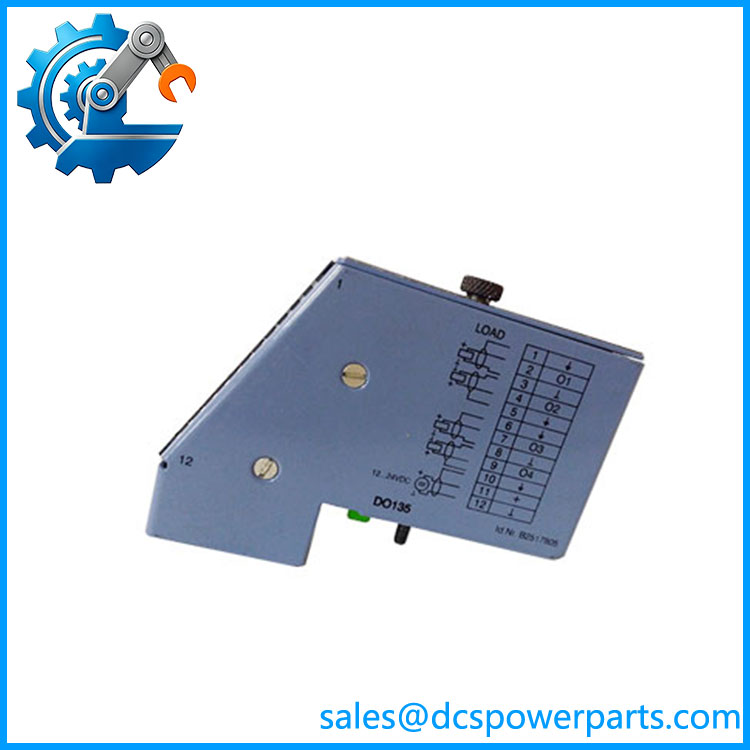
7DO135.70
Related Products
- B&R 7DO138.70 — A larger System 2003 digital-output module with eight 24 VDC outputs rated at 0.5 A. It provides substantially more output capacity, but its electrical architecture differs from the four-channel 7DO135.70.
- B&R 7DI135.70 — Four-channel digital input module from the same 2003 family. It handles 24 VDC input signals and includes high-speed/event-counter functions; it complements rather than replaces 7DO135.70.
- B&R 7DO164.70 — Four-output 2003 FET/Triac-related output module intended for different voltage and switching requirements. Its output characteristics should be checked carefully before considering substitution.
- B&R 7DO435.7 — Eight-channel configurable digital I/O architecture with FET outputs. It belongs to the broader B&R 2003 family but is not a drop-in replacement for the four-output DO135.
- B&R 7DO720.7 — Eight relay outputs for higher-voltage/current switching applications. This is a relay-output architecture rather than the semiconductor FET design used by 7DO135.
- B&R 7DO721.7 — Eight relay outputs with higher current capability than 7DO135. It may suit contactor or actuator loads that exceed the 0.1 A rating of the DO135, but the interface and application must be checked.
- B&R 7AF101.7 — AF101 adapter module used to connect B&R 2003 screw-in I/O modules to the CP interface arrangement. It is a supporting interface component rather than an alternative output card.
- B&R 7TB712.9 — 12-pin screw-clamp terminal block associated with the 2003 modules. It is an important procurement item because B&R documentation states that the terminal block must be ordered separately.
The Engineer’s Guide: Field Pitfalls to Avoid
⚠️ Do not mistake the 7DO135.70 for an 8-channel module.
The documented configuration is four FET outputs. Several inaccurate product listings describe this part as having 7 or 8 outputs, but those specifications conflict with B&R’s own product information and historical technical catalog.
⚠️ Do not exceed 0.1 A per output.
This is a low-current semiconductor output module. Check the actual coil/load current, including startup behavior, before connecting a field device. The total module current is also limited to 0.4 A.
⚠️ Do not forget the TB712 terminal block.
The output module itself does not necessarily constitute a complete field-connection assembly. B&R specifies a TB712 terminal block as a separately ordered accessory. Confirm whether the spare being purchased includes the required terminal hardware.
Practical check: Before replacement, record the four output assignments, load type, measured current, wiring polarity, and PLC configuration. After installation, test each output both unloaded and under its normal field load. For high-frequency applications, verify the actual pulse behavior rather than checking only the LED indication.
Frequently Asked Questions (FAQ)
What is B&R 7DO135.70 used for?
The 7DO135.70 is a four-channel digital output module for the B&R 2003 system. Its FET outputs switch 12–24 VDC loads and can operate at frequencies up to 100 kHz, making it suitable for both standard machine outputs and faster pulse-oriented applications.
How many outputs does 7DO135.70 have?
It has four FET outputs. This is confirmed by B&R’s product documentation. Some online listings incorrectly state seven or eight channels, so those descriptions should not be used for procurement specifications.
What is the maximum output current?
Each output is rated for 0.1 A maximum, with a maximum combined module current of approximately 0.4 A. The 30 VDC maximum switching voltage should also not be exceeded.
Can 7DO135.70 drive a 24 VDC solenoid?
Potentially, but only if the solenoid’s actual current consumption remains within the module’s output rating. Check the coil current under operating conditions, not just its nominal voltage. If the load approaches or exceeds 0.1 A, a higher-current output architecture should be considered.
Is 7DO135.70 compatible with the B&R X20 system?
Do not assume so. The 7DO135.70 belongs to the B&R 2003 screw-in module family, not the X20 modular I/O family. The interface, mounting method, electrical architecture, and engineering environment are different.
Does the 7DO135.70 include the terminal block?
B&R documentation specifies the TB712 terminal block as a separately ordered item. When sourcing a replacement, confirm whether the quoted unit includes the terminal hardware or only the electronic module.