Description
Bosch Rexroth VT-VRRA1-527-20/V0/2STV
Product Introduction
The Bosch Rexroth VT-VRRA1-527-20/V0/2STV is an analog valve amplifier designed to control high-response hydraulic valves with electrical position feedback. Bosch Rexroth identifies material number 0811405063 for this exact amplifier configuration. The 527 designation corresponds to the size-6 valve group, while the 2X component series retains the specified technical data and pin assignment across series 20 through 29. The amplifier is supplied from 24 VDC and uses an analog command-value signal.
The Bosch Rexroth VT-VRRA1-527-20/V0/2STV provides a controlled output stage and closed-loop valve-position control. Its design includes cable-break detection for the actual-value circuit, an enable input, short-circuit-protected outputs, and adjustment of the valve zero point. Bosch Rexroth documentation specifically lists the /2STV version for pilot-operated high-response valves such as the 4WRL and 3WRCB families. This makes the card part of the hydraulic control loop rather than a general-purpose PLC analog output module.
For replacement work, the exact suffix is important. The Bosch Rexroth VT-VRRA1-527-20/V0/2STV should not be replaced simply with another VT-VRRA1 card because different variants are assigned to different valve types and feedback arrangements. The electrical connector, valve solenoid requirements, feedback circuit, command-value range, and host card carrier should all be checked before installation. Bosch Rexroth specifies the open VT 3002-1-2X/32F card holder for this amplifier family.
Technical Specifications
| Parameter | Specification |
|---|---|
| Product Model | VT-VRRA1-527-20/V0/2STV |
| Material Number | 0811405063 |
| Manufacturer | Bosch Rexroth |
| Product Type | Analog hydraulic valve amplifier |
| Product Family | VT- |
| Component Series | 2X |
| Valve Size | NG6 / Size 6 |
| Control Method | Analog |
| Supply Voltage | 24 VDC |
| Command Value | 0–10 V |
| Electrical Connector | 32-pin DIN 41612 Form F |
| Board Format | Eurocard |
| Valve Feedback | Electrical position feedback |
| Control Characteristic | Closed-loop PID position control |
| Maximum Solenoid Current | 2.7 A |
| Typical Power Consumption | Approx. 37 W |
| Operating Temperature | 0 to +70°C |
| Dimensions | 100 × 160 × approx. 35 mm |
| Weight | Approx. 0.36 kg |
| Card Holder | VT 3002-1-2X/32F |
| Typical Valve Families | 4WRL and 3WRCB configurations specified by Bosch Rexroth |
| Communication Protocol | None; analog control electronics |
| Mounting | Card holder / 19-inch rack installation |
| Protection Rating | Not applicable as a standalone IP-rated field device |
Bosch Rexroth’s published material identifies the exact 0811405063 amplifier, its valve compatibility, 24 V supply, Eurocard format, and 32-pin Form F connector. A Bosch Rexroth-focused product listing also reports 2.7 A maximum solenoid current, approximately 37 W consumption, and 0–70°C operation.
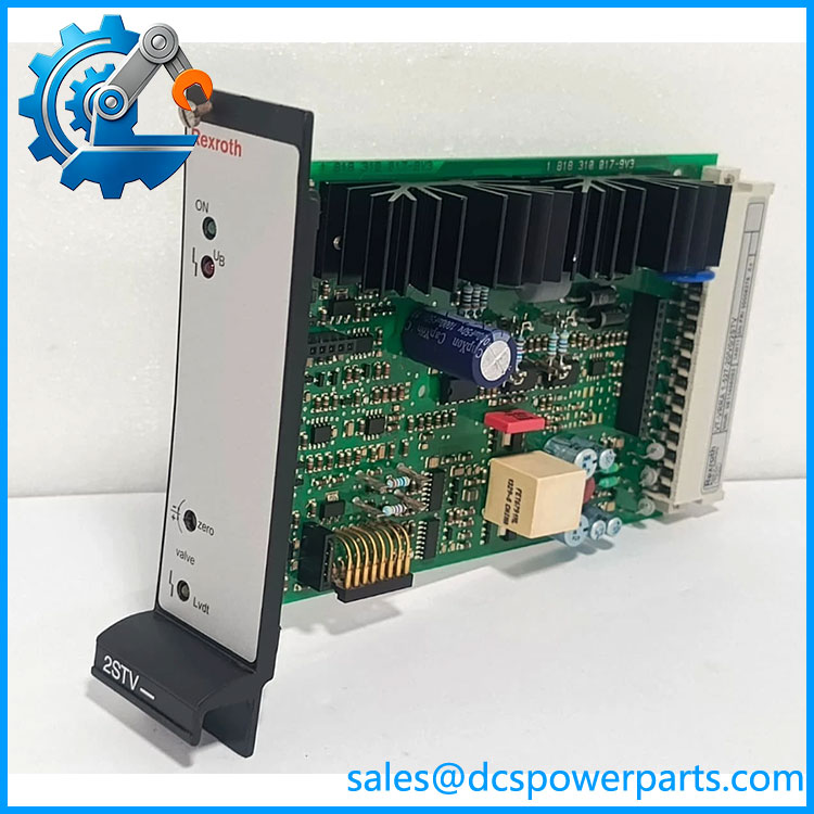
VT-VRRA 1-527-20/V0/2STV
Main Features and Engineering Considerations
Closed-loop hydraulic valve control
The VT- is not simply a current-output card. It combines the command signal with electrical valve-position feedback to regulate the valve. Bosch Rexroth describes the control as having PID characteristics, allowing the amplifier to regulate the valve position within the hydraulic control loop.
Exact 527 / 2STV configuration
The 527 portion identifies the size-6 configuration, while /2STV identifies the specified pilot-operated valve option. Bosch Rexroth lists 0811405063 specifically for several 4WRL and 3WRCB valve configurations. This makes the complete ordering code important during procurement.
Analog command interface
The amplifier receives an analog command-value signal. Available documentation identifies a 0–10 V command input for the 527 configuration. It is therefore normally controlled by an upstream motion, machine-control, or analog control system rather than through Ethernet, PROFIBUS, or another fieldbus.
Electrical feedback supervision
The amplifier monitors the electrical feedback circuit and provides cable-break detection. This is particularly relevant during troubleshooting because a fault in the LVDT/feedback wiring can prevent correct valve positioning even when the command signal and 24 V supply are present.
Controlled output stage
The valve output stage is controlled rather than being a simple switched output. The published documentation specifies short-circuit protection and a maximum valve solenoid current of approximately 2.7 A.
Legacy Eurocard architecture
The 100 × 160 mm Eurocard format and DIN 41612 Form F connector indicate an older cabinet-based hydraulic control architecture. The module is intended for an appropriate card holder rather than direct DIN-rail mounting. Bosch Rexroth specifies the VT 3002-1-2X/32F holder for the family.
Application Scenarios
- High-response hydraulic valve control
- Hydraulic servo positioning
- Machine-tool hydraulic control
- Press and forming machinery
- Injection and plastics machinery
- Closed-loop hydraulic actuator control
- Hydraulic position control
- Industrial motion-control systems
- 4WRL valve control
- 3WRCB valve control
- Legacy Bosch Rexroth hydraulic control cabinets
Engineer’s Guide: Field Pitfalls
Do not treat this as a generic PLC analog output module. The VT- contains the valve-control electronics and feedback loop required by the specified hydraulic valve.
Verify the complete valve model. Bosch Rexroth specifically lists different compatible valve configurations for 0811405063. A visually similar 4WRL or related valve is not sufficient evidence of compatibility.
Check the feedback wiring. The amplifier depends on electrical valve-position feedback. A cable-break indication can point toward the LVDT circuit, connector, or field wiring rather than a failed amplifier.
Check the command signal before replacing the card. Confirm that the upstream controller actually provides the expected analog command signal and that the signal reference is wired correctly.
Verify the 24 VDC supply under load. A nominal 24 V reading with the card disconnected does not prove that the supply remains within an acceptable range when the amplifier and valve circuit are energized.
Check the card holder. The module uses a 32-pin Form F connector and the specified VT 3002 card-holder architecture. Poor connector contact can create intermittent feedback or valve-output faults.
Do not mix VT- variants casually. The family includes different type numbers, valve sizes, component series, and options. The 527-20/V0/2STV configuration should be matched against the machine’s original documentation.
Check valve zero adjustment. The amplifier provides a valve-zero adjustment. Record the existing setting before replacement when plant procedures permit, then verify the hydraulic neutral position after commissioning.
Test the hydraulic system after electrical replacement. Correct amplifier LEDs and electrical measurements do not prove that the valve is hydraulically centered or that the actuator will respond correctly under load.
Frequently Asked Questions
What is Bosch Rexroth VT–527-20/V0/2STV?
It is an analog hydraulic valve amplifier for high-response valves with electrical position feedback. Its Bosch Rexroth material number is 0811405063.
What valves does 0811405063 support?
Bosch Rexroth lists 4WRL 10…35 V/V1…M-3X, 4WRL 10…35 E/W…S-3X, 4WRL 10…25 V/V1…M-3X-750, and 3WRCB 25…50…M-1X configurations for the /2STV version.
What is the supply voltage?
The documented supply voltage is 24 VDC.
What is the command input?
The amplifier uses an analog command-value input; available specifications identify 0–10 V for this configuration.
What connector does it use?
It uses a 32-pin DIN 41612 Form F connector and is designed for an appropriate card holder or 19-inch rack arrangement.
Does it communicate over PROFIBUS or Ethernet?
No. This is an analog valve amplifier, not a network communication module. The control interface is based on analog command and electrical valve feedback.
What is the maximum valve solenoid current?
Available documentation lists approximately 2.7 A maximum valve solenoid current for this amplifier family.
What is the operating temperature?
Published specifications give 0 to +70°C for the VT- configuration.
Procurement Note
Specify the part as:
Boschoth VT-/V0/2STV — Material No. 0811405063 — Analog Hydraulic Valve Amplifier
Before approving a replacement, verify:
- Complete part number:
- Material number: 0811405063
- Valve manufacturer and exact valve model
- Valve size / NG6 configuration
- Electrical position-feedback type
- 24 VDC supply
- 0–10 V command signal
- 32-pin DIN 41612 Form F connector
- Card-holder model
- Valve solenoid current requirement
- Existing zero-point setting
- Feedback cable condition
- Component-series marking
- Board revision and nameplate
The critical procurement point is the complete ordering code. Bosch Rexroth’s documentation distinguishes the 527, 2X, V0, and 2STV elements, and the /2STV version has specific valve compatibility. A generic “VT–527” replacement is not enough to establish interchangeability.