Description
Product introduction
In legacy hydraulic machinery, the amplifier board translates control commands into electrical signals used by the hydraulic control system. The Bosch Rexroth VT-TSPD-1-10/V0/0 is identified as an analog command-value module and digital amplifier, making it relevant to maintenance of equipment that relies on its original electronic control architecture.
When sourcing the Bosch Rexroth VT-TSPD-1-10/V0/0, match the full catalog designation and board markings. The /V0/0 suffix is important for identification, and a similar-looking Rexroth amplifier may use different inputs, control logic, or hardware revisions. Verify the original machine documentation before approving a replacement.
Key technical specifications
| Parameter | Specification |
|---|---|
| Product model | VT-TSPD-1-10/V0/0 |
| Manufacturer | Bosch Rexroth |
| Product type | Analog command-value module / digital amplifier |
| Product form | Electronic control board |
| System application | Hydraulic control |
| Command input range | Not verified for this exact model suffix |
| Supply voltage | Not verified |
| Output configuration | Confirm from the matching schematic |
| Communication interface | Not established for this exact variant |
| Mounting method | Confirm board format and rack or enclosure requirements |
| Operating temperature | Refer to the applicable Rexroth documentation |
| Protection rating | Not established for the board itself |
| Lifecycle status | Listed as discontinued by industrial parts references |
Exact electrical ratings and terminal assignments should be taken from the matching technical documentation rather than inferred from other VT-series amplifier models.
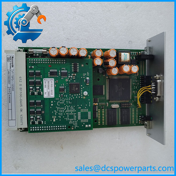
VT-TSPD-1-10V00
Application scenarios and maintenance considerations
- Legacy hydraulic equipment: Maintenance of machines that retain the original Rexroth electronic control board.
- Hydraulic command processing: Control systems that require an analog command-value module as part of their established control architecture.
- Industrial machine repair: Replacement of a faulty amplifier board when the original configuration must be preserved.
- Spare-parts inventory: Procurement planning for discontinued electronic modules used in long-service machinery.
Field note: Before replacement, document the board’s connector layout, installed jumpers, configuration settings, and revision markings. A physically compatible board may not have the same signal scaling or control behavior.
Related product identification
The broader Bosch Rexroth VT family includes several digital valve amplifiers, but shared family naming does not establish interchangeability. For example, the VT-VSPD-1 family is described in separate technical references with specific command-input and control functions; it should not be treated as a direct substitute without a documented compatibility match.
Engineer’s replacement checklist
- Confirm the exact part number: Check the full
VT-TSPD-1-10/V0/0marking and any additional board or revision codes. - Compare electrical connections: Verify supply requirements, command-signal range, output connections, and pin assignments from the correct schematic.
- Check configuration and test results: Record jumpers and settings, inspect connectors and PCB condition, and validate control behavior using the machine’s approved commissioning procedure.
Frequently asked questions
1. What is the VT-TSPD-1-10/V0/0?
It is identified as a Bosch Rexroth analog command-value module and digital amplifier board for industrial hydraulic control applications.
2. Is VT-TSPD-1-10V00 the same designation?
It appears to be a compact rendering of VT-TSPD-1-10/V0/0. Confirm the physical label to avoid confusing zeros, letter O characters, or suffix differences.
3. Is the module discontinued?
Industrial parts references list it as discontinued by the manufacturer. Current stock status and the condition of any available unit should be confirmed before procurement.
4. Can another Rexroth VT-series amplifier replace it?
Not automatically. Verify the input signals, electrical connections, output behavior, configuration, and documented compatibility with the installed machine.
5. What should buyers provide to verify a replacement?
Provide a clear photo of the complete part label, PCB markings, connector side, and the original equipment or control cabinet identification.
6. What should be checked before returning the machine to service?
Confirm correct installation and wiring, verify configuration against the original documentation, and perform the approved functional tests before resuming production.