Description
Key Technical Specifications
| Parameter | Specification |
|---|---|
| Model | RCM475LY-13 |
| BENDER ordering number | B 9401 2035 |
| Monitoring function | Residual current / ground fault monitoring |
| Monitored system | Single-phase or three-phase AC |
| System grounding | TN, TT; HRG applications within rated range |
| Supply voltage | 90–132 VAC |
| Supply frequency | 50/60 Hz |
| Supply operating range | 0.85–1.1 × rated supply voltage |
| Power consumption | ≤ 3 VA |
| Adjustable response range | 10 mA–10 A |
| Response delay | 0–10 seconds |
| Delay accuracy | ±20% |
| Hysteresis | Approximately 20% |
| Integrated current transformer | 18 mm aperture |
| Measuring channels | 1 |
| Alarm output | 1 DPDT relay |
| Relay operation | Normally energized or de-energized, selectable |
| Alarm memory | Latching or non-latching, selectable |
| Indication | LED bar graph, Power On LED, Alarm LED |
| Test/reset | Integrated button and external connection |
| Terminal connection | Screw terminals |
| Operating temperature | -10 to +55°C |
| Internal protection | IP30 |
| Terminal protection | IP20 |
| Mounting | DIN rail or screw mounting |
| Dimensions | Approximately 99 × 70 × 45 mm |
| Weight | ≤350 g |
Product Introduction
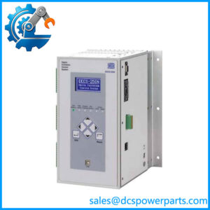
The BENDER RCM475LY-13 is intended for continuous monitoring of residual current in grounded AC electrical distribution systems. Its integrated 18 mm current transformer measures the imbalance between the current-carrying conductors routed through the sensing aperture. When the measured residual current exceeds the configured response threshold and the selected delay expires, the unit activates its alarm indication and DPDT output relay.
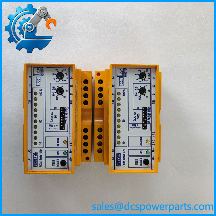
RCM475LY-13
The adjustable 10 mA–10 A response range allows the RCM475LY-13 to serve applications with different ground-fault monitoring requirements. The device also provides a percentage-based LED bar graph, selectable relay behavior, fault latching, and internal or external test/reset operation. Its internal current-transformer circuit is monitored continuously; a broken sensing circuit causes an alarm relay response and a flashing Alarm LED. This feature is important when troubleshooting installations where a wiring fault could otherwise compromise monitoring.
Application Scenarios and Field Pitfalls
Typical applications
- Ground-fault monitoring in industrial AC distribution panels.
- Single-phase and three-phase motor circuits and motor control centers.
- Generator installations, including fixed and portable equipment.
- Electrical alarm systems and control cabinets.
- Heat-tracing circuits and general industrial power systems.
- HRG systems where the expected residual-current level falls within the monitor’s response range.
fournias-bender
Important installation checks
- Route conductors correctly. All current-carrying conductors, including neutral when used, must pass through the integrated current transformer. Do not route the protective ground conductor through it.
- Check the aperture. The integrated transformer has an 18 mm opening. Confirm that the complete conductor arrangement fits without damaging insulation or compromising cable routing.
- Do not confuse supply voltage with monitored circuit voltage. The
-13suffix identifies the 90–132 VAC auxiliary supply version. It does not mean the monitored power circuit is limited to 132 VAC. - Set the response threshold and delay carefully. A threshold that is too low can cause nuisance alarms from normal leakage current; excessive delay can postpone fault notification.
- Verify relay behavior. Confirm normally energized/de-energized operation and latching/non-latching settings against the plant alarm philosophy.
- Test after installation. Use the specified test procedure and verify the actual alarm relay response. Installation and commissioning should be performed by qualified electrical personnel.
Related Products and Model Differences
| Model | Main difference |
|---|---|
| RCM475LY | 230 VAC supply version; 10 mA–10 A response range |
| RCM475LY-21 | 9.6–84 VDC supply version; 10 mA–10 A response range |
| RCM475LY-71 | 230 VAC supply; 6–600 mA response range |
| RCM475LY-7113 | 90–132 VAC supply; 6–600 mA response range |
| RCM470LY | Related residual current monitor family using an external current transformer |
These are related variants, not confirmed direct replacements. In particular, RCM475LY-7113 is not an equivalent substitute for RCM475LY-13 because its adjustable response range is different.
Procurement and Quality Control
The RCM475LY-13 appears in BENDER’s product catalog under ordering number B 9401 2035. A secondary industrial parts listing reports the model as discontinued by the manufacturer. Current OEM support and replacement availability should therefore be confirmed before planning a long-term maintenance strategy.
Before purchasing, request:
- A photograph of the complete model and ordering-number label.
- Confirmation of the 90–132 VAC supply version.
- Confirmation that the current transformer aperture is undamaged.
- Inspection of screw terminals, housing, and mounting clips.
- Power-up and alarm LED test results.
- Functional test evidence for the DPDT relay.
- Confirmation of response-threshold, delay, and relay configuration.
- Clear disclosure of whether the unit is new old stock, unused surplus, or refurbished.
Replacement decision: Match both RCM475LY-13 and B 9401 2035. Do not approve a substitute based only on the RCM475LY family name; supply voltage, response range, and relay behavior must all match the installed protection scheme.