Description
Technical Specifications
| Parameter | Specification |
|---|---|
| Product Model | SDCS-AMC-DC-2 |
| ABB Part Number | 3ADT312700R0001 |
| Manufacturer | ABB |
| Product Type | DC drive application motor control board |
| Drive System | ABB DCS 600 |
| Required Control Board | SDCS-CON-2 |
| Documented Software Requirement | S15.xxx |
| Controller Function | Speed regulation and torque-reference generation |
| Optical Channels | 3 |
| Maximum Optical Channel Transmission Rate | Up to 4 Mb/s per channel, per ABB technical documentation |
| Channel 0 | Communication with higher-level control systems |
| Channel 2 | Master-follower communication |
| Channel 3 | Drive/PC communication for maintenance and diagnostics |
| Power Supply | Supplied within the drive system; confirm installation documentation |
| Mounting | Internal drive control assembly |
| Product Net Weight | 0.1 kg, according to ABB catalog data |
ABB’s technical documentation is the primary reference for the board’s intended role and system requirements. Confirm optical component variants and channel configuration against the specific board revision before installation.
Product Overview
The ABB SDCS-AMC-DC-2 3ADT312700R0001 is an application motor control and communication board designed for compatible ABB DC drive systems. It contains its own controller and supports speed regulation, torque-reference generation, control functions, and data exchange with the main drive controller. ABB documentation specifies that the board must be used with a DCS 600 module equipped with an SDCS-CON-2 control board and S15.xxx software. This requirement is central to replacement planning; the part number alone does not establish compatibility with every ABB DC drive generation.
The board’s control structure has two main sections. One implements the speed regulator and associated functions used to produce a torque reference. The other supports application-specific control and regulation functions. The board processes incoming data, sends the resulting torque reference to the CON-2 board, and evaluates actual operating values for transmission to the higher-level control system. This arrangement supports coordinated drive operation within the documented system architecture.
Three optical communication channels serve different purposes. Channel 0 carries data between the higher-level control and the drive system. Channel 2 supports master-follower applications in which multiple drives operate in coordination. Channel 3 provides a connection for the DriveWindow PC tool used in commissioning and maintenance. ABB’s technical documentation lists a maximum transmission speed of 4 Mb/s per optical channel; optical components and connection requirements must be checked against the specific installation.
For maintenance teams, the practical priority is to match the replacement board to the installed drive hardware, control software, and optical communication arrangement. A physically compatible board may still be unsuitable if its configuration differs from the original. Confirm the SDCS-CON-2 version, software requirements, connector arrangement, and master-follower topology before ordering or installing the SDCS-AMC-DC-2 3ADT312700R0001.
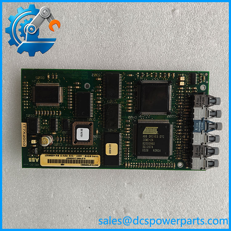
SDCS-AMC-DC-2 3ADT312700R0001
Major Features and Advantages
1. Speed regulation and torque-reference generation
The board implements speed-regulation functions and produces a torque reference for the main drive control board. The actual control behavior depends on the installed software and application configuration. Do not assume that all drive applications use identical regulator settings.
2. Application-specific control functions
ABB documentation describes a second software section that can be programmed for application-specific control and regulation. This allows the board to participate in engineered drive applications beyond basic speed regulation. The supported functions should be verified from the original project documentation.
3. Optical communication with higher-level controls
Channel 0 provides the communication path between higher-level control equipment and the DCS 600 drive. ABB documentation identifies possible control sources such as FCI, APC2, AC80, fieldbus adapter modules, and AC 800M. The actual interface depends on the installed architecture and any required adapter hardware.
4. Master-follower drive coordination
Channel 2 is used for master-follower communication, supporting applications where two or more drives operate in a coordinated relationship. The correct optical components, cable type, and connection topology must match the hardware and drive arrangement.
5. DriveWindow maintenance connection
Channel 3 provides a connection for the DriveWindow PC tool, which is used for drive commissioning and maintenance. Confirm the required optical interface and software version before attempting to connect a service computer.
6. Defined system compatibility
The documented pairing with the SDCS-CON-2 board and S15.xxx software gives engineers a concrete starting point for compatibility checks. This is more reliable than selecting a board based solely on its description as an ABB DC drive controller.
Applications
The ABB SDCS-AMC-DC-2 3ADT312700R0001 is relevant to DC drive installations that use the documented DCS 600 control architecture. Typical application contexts include:
- Coordinated multi-drive systems: Master-follower arrangements in which drive commands and operating values must be exchanged between dependent drives.
- Industrial material handling: Compatible drive systems used in cranes and other equipment requiring coordinated motor control.
- Steel and metal processing: DC drive installations where speed regulation and coordinated drive behavior are part of the machine design.
- Paper and converting machinery: Drive sections that require coordinated operation under an established control architecture.
- Drive maintenance and commissioning: Replacement of an existing board or access to drive information through the supported DriveWindow interface.
- Legacy DC drive support: Maintenance of installed DCS 600 systems where the original hardware, software, and optical communication arrangement are still in service.
These examples describe the types of applications in which ABB DC drive systems may be used; they do not establish compatibility with every machine or drive model. The board’s suitability must be determined from the actual installed control configuration.
Before selecting the part, verify the drive model, SDCS-CON-2 control board, S15.xxx software requirement, and optical channel assignments. If the installation uses a master-follower link, check the channel 2 arrangement and the optical components at both ends. If the board is being replaced after a fault, review the drive fault history and communication diagnostics rather than assuming the board itself was the sole cause.
The SDCS-AMC-DC-2 3ADT312700R0001 should not be treated as a generic PLC controller or a direct replacement for another SDCS-AMC generation without documented compatibility evidence.
Related Products
| Model / Reference | Relationship |
|---|---|
| SDCS-CON-2 | Required main control board identified in ABB’s compatibility documentation. |
| DCS 600 | DC drive system specified for use with the SDCS-AMC-DC-2 under the documented configuration. |
| FCI | Higher-level control interface identified as a possible data source for channel 0. |
| APC2 | Higher-level control equipment referenced in the ABB communication architecture. |
| AC80 | ABB controller family identified as a possible higher-level control source. |
| AC 800M | Controller family that can communicate through the documented system arrangement or suitable interface modules. |
| Nxxx fieldbus adapters | Adapter modules that may provide an interface between external controllers and the drive system. |
| DriveWindow | PC tool used for drive commissioning and maintenance through the supported interface. |
These are related control-system components and tools, not interchangeable substitutes for the 3ADT312700R0001.
Installation and Maintenance
Before replacing the ABB 3ADT312700R0001, record the drive model, installed board, software version, optical cable connections, and existing master-follower arrangement. Confirm that the replacement matches the original part number and is suitable for the installed hardware and software.
Isolate the drive using the site’s approved electrical safety and lockout/tagout procedures. DC drive systems can retain hazardous energy after the incoming supply is disconnected. Follow the manufacturer’s discharge and verification procedures before accessing internal electronics. Use appropriate electrostatic-discharge precautions when handling the control board.
Before removing the original board, document the optical channel connections and inspect the fiber-optic cables and connectors. Optical components may differ by transmission rate and interface requirements, so do not select or substitute cables based on appearance alone. Confirm that the channel 0, channel 2, and channel 3 connections match the approved drawings.
After installation, verify board seating, connectors, optical links, and the approved software configuration. Restore settings only from validated backups or authorized engineering records. Perform the required commissioning checks for speed regulation, torque-reference transfer, drive communication, and master-follower operation where applicable. Review fault diagnostics before returning the equipment to production.
Record the replacement part number, software version, optical configuration, and test results in the maintenance history. If communication or regulation faults persist, investigate the associated control board, optical link, and drive configuration rather than repeatedly replacing the AMC board without further diagnosis.
Product Assurance
For the ABB 3ADT312700R0001, assurance should focus on exact identification and compatibility with the installed DCS 600 system. Verify the complete part number and physical revision, and confirm the and S15.xxx software requirements against the original drive documentation. ABB’s catalog identifies the part as an SDCS-AMC-DC2 control unit and marks it as no longer for sale, making accurate legacy-spare identification especially important.
Before purchase, request photographs of the actual board label, optical components, and connectors where possible. The supplier should disclose whether the unit is new, unused surplus, refurbished, or used. Any test report should describe the actual checks performed; visual inspection alone does not demonstrate successful operation in a specific drive configuration.
Where a board-level functional test is unavailable, that limitation should be stated clearly. Confirm return and warranty terms in writing and retain the original board’s identification and fault history to support troubleshooting.
Final acceptance should depend on correct part-number verification, documented hardware and software compatibility, and successful commissioning checks. Do not assume that a seller’s general statement of compatibility with ABB DC drives establishes suitability for the exact installed system.