Description
Bently Nevada 3500/33 149986-01 + 149992-01
Product Introduction
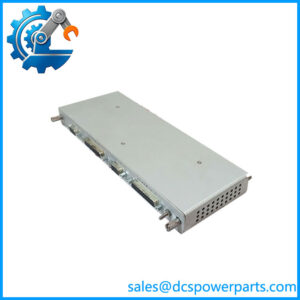
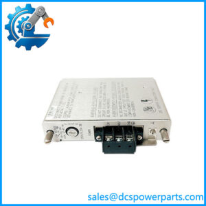
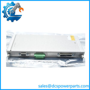
When a machinery protection rack has to turn monitor alarms into physical plant actions, software status alone is not enough. The Bently Nevada 3500/33 149986-01 + 149992-01 assembly provides 16 programmable relay outputs that can be driven from alarm, danger, Not-OK, and measured-variable conditions within the 3500 rack. This makes it the interface between the rack’s monitoring logic and external alarm, interlock, shutdown, or annunciation circuits.
The architecture is split between the control and output sections. 149986-01 performs the relay-control and logic functions, while 149992-01 contains the standard relay output hardware. Each output can have its own documented alarm-drive logic, while the relays are arranged in four groups of four with selectable normally energized or normally de-energized operation. For procurement, do not confuse this standard relay output configuration with the 149992-02 failsafe version or the low-current 149992-03/04 variants.
Key Technical Specifications
| Parameter | Specification |
|---|---|
| Manufacturer | Bently Nevada |
| Series | 3500 Machinery Protection System |
| Model | 3500/33 |
| Front Control Module | 149986-01 |
| Rear Output Module | 149992-01 |
| Product Type | 16-Channel Relay Module |
| Number of Relay Channels | 16 |
| Relay Type | SPDT / Form C |
| Relay Groups | 4 groups of 4 channels |
| Relay Mode | Normally De-energized (ND) or Normally Energized (NE) |
| Minimum Switched Current | 100 mA @ 5 VDC |
| Maximum Switched Current | 5 A |
| Maximum AC Switching Voltage | 250 VAC |
| Maximum DC Switching Voltage | 125 VDC |
| Maximum AC Switched Power | 1200 VA |
| Maximum DC Switched Power | 70 W |
| Relay Contact Life | 10,000 cycles under specified rated-load conditions |
| Typical Power Consumption | 5.8 W |
| Main Module Dimensions | 241 × 24.4 × 242 mm |
| Main Module Weight | Approx. 0.7 kg |
| I/O Module Dimensions | 241 × 24.4 × 99.1 mm |
| I/O Module Weight | Approx. 0.4 kg |
| Main Module Rack Space | 1 full-height front slot |
| I/O Rack Space | 1 full-height rear slot |
| Configuration Software | 3500 Rack Configuration Software v3.3 or later |
| Data Acquisition Software | 3500 Data Acquisition Software v2.40 or later |
The relay ratings above distinguish the standard relay contacts from the low-current versions. Bently Nevada’s datasheet specifies a 100 mA minimum switched load at 5 VDC for the standard silver contacts and up to 5 A switching current, with maximum switched power of 1200 VA AC and 70 W DC under the specified resistive-load conditions.
Major Features / Advantages
16 Independent Relay Channels
The 3500/33 provides 16 relay output channels in one rack module assembly. Each channel can be programmed independently for its alarm-drive function, allowing one module to handle multiple machinery protection outputs without requiring a separate relay interface for every monitored variable.
This is particularly useful where several protection decisions must be converted into hardwired plant signals. A single rack may need separate contacts for bearing vibration, shaft position, speed, temperature, overspeed-related conditions, or general monitor status. The 3500/33 gives the engineering team a configurable relay layer between those monitor states and the external control circuitry.
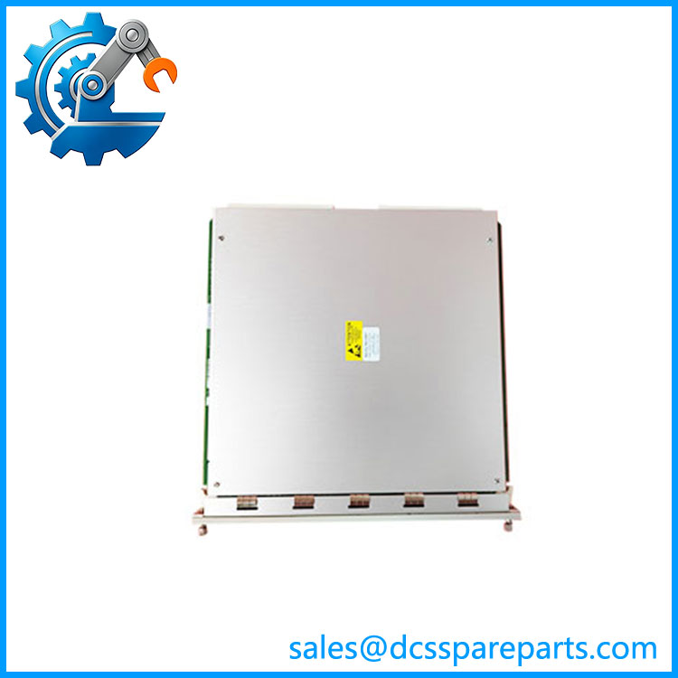
149986-01
Programmable Alarm-Drive Logic
The relay control section can use alarm and danger conditions, Not-OK status, and individual measured variables from compatible monitor channels as logic sources. AND/OR logic can be assigned according to the protection design.
This is one of the more important characteristics of the module. The 3500/33 is not simply a 16-channel collection of fixed contacts. The logic is part of the module’s function, so the configuration file becomes an important part of the maintenance record.
Normally Energized or Normally De-Energized Operation
The 16 relays are organized into four groups of four channels. Each group can be switch-selected for Normally Energized (NE) or Normally De-energized (ND) operation.
That arrangement gives engineers flexibility when designing alarm and shutdown circuits, but it also introduces a commissioning issue: the physical relay-mode selection and the intended plant trip philosophy must agree. A software configuration can be correct while a hardware mode switch is wrong.
Standard Relay Output Architecture
The 149992-01 is specifically the standard 16-channel relay output module. Bently Nevada also lists separate 149992-02 failsafe, 149992-03 low-current, and 149992-04 low-current failsafe output modules.
This distinction is important for replacement work. A failsafe or gold-contact low-current variant may look similar but has a different electrical application. Do not substitute one solely because the connector and mechanical form appear identical.
Epoxy-Sealed Relay Construction
Published 3500/33 documentation identifies the relay outputs as epoxy-sealed. The standard relay configuration also includes an arc suppressor. These design features are relevant when the module is being used for repeated industrial switching rather than merely low-level status indication.
The relay rating still has to be respected. An epoxy-sealed relay is not a reason to exceed the specified current, voltage, or switched-power limits.
Direct Interface to External Protection Circuits
The relay contacts can be used to interface the 3500 protection system with external annunciators, interlocks, shutdown circuits and control-system inputs. The exact wiring depends on whether the circuit is designed around normally energized or normally de-energized operation.
For critical machinery shutdowns, the wiring philosophy should be reviewed as a complete safety function. The 3500/33 provides relay contacts; it does not by itself make an entire shutdown circuit SIL-rated or otherwise safety-certified.
Established 3500 Software Integration
The 3500/33 requires 3500 Rack Configuration Software version 3.3 or later, with 3500 Data Acquisition Software version 2.40 or later and 3500 Data Display Software version 1.40 or later identified in the published ordering considerations. When used with 3500/93 or 3500/94 display modules, corresponding firmware requirements also apply.
For a legacy installation, this matters more than the nominal card revision. Before replacing a relay module, record the existing rack configuration and verify that the available engineering workstation can communicate with the replacement.
Application Scenarios & Pain Points
Turbine Protection
Steam and gas turbine systems commonly require physical relay outputs for alarm annunciation, trip logic and external control interfaces. The 3500/33 can translate conditions already detected by the 3500 monitoring rack into dedicated relay states.
Compressor Trains
Compressor protection systems often contain multiple monitored variables with different alarm priorities. The 16-channel relay architecture allows individual alarm or status conditions to be assigned to separate external circuits.
Pump and Fan Machinery
For plant rotating equipment, relay outputs can provide hardwired alarm or shutdown signals to external control equipment. The important engineering task is matching the relay contact arrangement to the receiving circuit rather than assuming every DCS digital input can be wired identically.
Legacy 3500 Rack Replacement
This is the most procurement-sensitive application. If an installed system contains 149986-01 + 149992-01, the replacement should preserve the standard relay output architecture. Ordering a 149992-02 because it is also labeled a 3500/33 relay module can change the failsafe behavior. Ordering a 149992-03 or 149992-04 changes the contact characteristics.
Related Products
- 149992-02 — 16-channel failsafe relay output module; different relay behavior from the standard 149992-01.
- 149992-03 — Low-current 16-channel relay output module using the low-current relay configuration.
- 149992-04 — Low-current 16-channel failsafe relay output module.
- 00580453 — 16-position green connector header for internal termination.
- 166M2381 — Push-in-spring connector-header alternative identified in current 3500/33 documentation.
- 3500/22M — Transient Data Interface for rack-level data acquisition; complementary rather than a relay-output substitute.
- 3500/32M — 4-channel relay module family for applications requiring fewer relay outputs.
- 3500/34 — TMR relay module for applications requiring a triple-modular-redundant relay architecture; the standard 3500/33 is not a TMR relay module.
Engineer’s Guide: Field Pitfalls to Avoid
1. Do not treat 149986-01 and 149992-01 as interchangeable parts.
They are the control and output portions of the 3500/33 architecture. The manufacturer identifies 149986-01 as the spare relay control module and 149992-01 as the spare relay output module.
2. Verify the relay variant before ordering.
149992-01 is the standard relay output module. 149992-02 is failsafe, while 149992-03 and 149992-04 are low-current variants. These are functional differences, not cosmetic suffixes.
3. Check ND/NE selector settings.
The four groups of four relays can be selected for Normally De-energized or Normally Energized operation. A replacement that has the wrong physical selection can produce unexpected alarm or trip behavior even when the software configuration is correct.
4. Do not exceed the contact ratings.
For the standard relay configuration, published limits include 5 A maximum switched current, 250 VAC maximum switched voltage, 125 VDC maximum switched voltage, 1200 VA maximum AC switched power and 70 W maximum DC switched power under the specified conditions. Check the actual load type before wiring the contact directly into a field circuit.
5. Do not confuse relay logic with safety certification.
The module can implement programmable alarm-drive logic, but the complete machinery trip function depends on the overall architecture, wiring, configuration, associated monitors and application-specific safety design.
6. Preserve the configuration before replacing the module.
Record the relay assignments, AND/OR logic, alarm sources, Not-OK behavior, relay mode and external wiring. A physically correct spare does not automatically reproduce the original application configuration.
7. Do not hot-insert the module without following the rack procedure.
The current Bently Nevada documentation specifically warns against hot insertion for the relay module. A relay card connected to an active trip circuit should be treated as an energized protection component, not as an ordinary I/O card.
8. Verify the approval suffix from the actual assembly.
The 3500/33 ordering structure uses an output-module option plus an agency-approval option. The spare numbers 149986-01 + 149992-01 alone do not establish the hazardous-area approval configuration.
FAQ
What is the Bently Nevada 3500/33 149986-01 + 149992-01?
It is a 3500/33 16-channel relay module assembly consisting of the 149986-01 relay control module and 149992-01 standard relay output module. Bently Nevada lists both as dedicated 3500/33 spare parts.
What is the difference between 149986-01 and 149992-01?
149986-01 is the relay control section, while 149992-01 is the relay output section containing the standard relay hardware. The two work together as the 3500/33 relay architecture.
How many relay outputs does the 3500/33 provide?
The standard 3500/33 provides 16 relay channels, arranged as four groups of four. Each channel can be assigned its own alarm-drive logic.
Is 149992-01 a failsafe relay module?
No. 149992-01 is the standard 16-channel relay output module. Bently Nevada identifies 149992-02 separately as the 16-channel failsafe relay output module.
What is the relay contact rating?
For the standard relay configuration, the published specifications give a maximum switched current of 5 A, maximum switched voltage of 250 VAC / 125 VDC, maximum switched power of 1200 VA AC / 70 W DC, and a minimum switched current of 100 mA at 5 VDC. Actual application limits should be checked against the load type and the applicable configuration.
What software version is required?
The published ordering information specifies 3500 Rack Configuration Software v3.3 or later, 3500 Data Acquisition Software v2.40 or later, and 3500 Data Display Software v1.40 or later. Additional firmware requirements apply when the rack uses 3500/93 or 3500/94 display modules.
Does 149986-01 + 149992-01 identify the complete hazardous-area configuration?
Not by itself. The 3500/33 ordering code includes a separate agency-approval option. The two spare part numbers establish the relay-control and standard-output hardware, but the installed rack’s complete approval configuration should be verified from its nameplate and documentation.
What should I verify before purchasing this replacement?
Confirm 3500/33, 149986-01, 149992-01, relay mode, existing alarm-drive configuration, external contact wiring, software compatibility and the rack’s agency-approval suffix. Also verify the actual inventory condition and hardware revision rather than assuming that a visually similar 3500/33 assembly is configured identically.