Description
Key Technical Specifications
| Parameter | Value |
|---|---|
| Manufacturer | Metso Automation / Valmet |
| Model | IOP341 |
| Assembly Number | 181543 |
| Product Type | Analog Output Module |
| System Family | maxPAC / Metso DNA DCS |
| Output Channels | 16 channels |
| Output Signal | 4–20 mA current output |
| Output Range | Configurable analog current output |
| Isolation | Channel and system isolation |
| Resolution | High-resolution D/A conversion |
| Output Monitoring | Channel diagnostics |
| Installation | maxPAC I/O rack |
| Communication | Internal DCS I/O bus |
| Application | Continuous process control |
Product Introduction
Metso IOP341 Overview
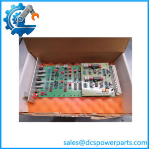
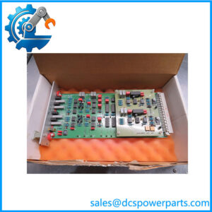
The Metso IOP341 181543 is an analog output module designed for the Metso maxPAC distributed control system architecture. It provides the electrical interface required to convert digital control commands generated by the DCS processor into analog signals used by field-level equipment. These signals are commonly applied for controlling process valves, actuator positioners, motor speed references, and other continuously adjustable devices.
The Metso IOP341 analog output module is designed for industrial applications where reliable transmission of control signals is required. Unlike discrete output modules that only provide ON/OFF commands, analog output modules allow precise adjustment of process variables by transmitting proportional signals such as 4–20 mA.
The Metso IOP341 181543 operates as part of the complete maxPAC I/O system. The module receives commands from the controller through the internal I/O communication structure and outputs corresponding analog values to connected field devices. Correct operation depends on proper configuration within the Metso DNA engineering database, correct channel assignment, and accurate field wiring.
The Metso Automation IOP341 is commonly installed in long-service process plants where maxPAC and Metso DNA systems continue to control production equipment. Typical applications include flow regulation, pressure control, temperature loops, and equipment speed adjustment.
When replacing a , engineers should verify the existing module configuration, output channel assignments, field device requirements, and control database parameters. A replacement module with matching hardware specifications may still require correct software configuration before returning the process loop to normal operation.
The analog output module should be evaluated as part of the complete control loop. Problems appearing as output failures may originate from the controller, communication bus, terminal connections, external power supply, or the connected field actuator rather than the module itself.
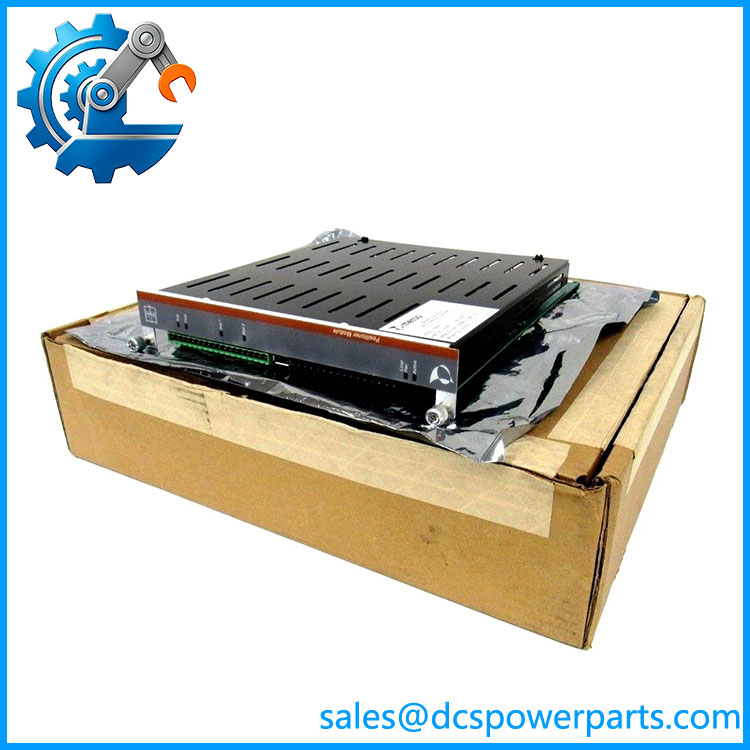
IOP341
Application Scenarios & Field Considerations
Engineering Pain Point
Typical issues associated with modules include:
- Control valve position errors
- Loss of analog output signal
- Incorrect actuator response
- Channel diagnostic alarms
- Process loop instability
Possible causes include:
- Output channel failure
- Incorrect DCS scaling
- Damaged field wiring
- Actuator input problems
- Incorrect loop configuration
Recommended troubleshooting steps:
- Check module diagnostic indicators
- Verify DCS output scaling
- Measure 4–20 mA loop current
- Inspect terminal wiring
- Confirm field device input range
- Compare engineering database settings
The is only one element in the analog control chain. Reliable operation requires correct interaction between the DCS controller, I/O module, wiring, and field equipment.
Typical Applications
Process Control Loops
Used for:
- Flow control valves
- Pressure regulators
- Temperature control systems
Pulp and Paper Automation
Applied for:
- Machine speed adjustment
- Chemical dosing control
- Process actuator positioning
Power Generation
Used for:
- Boiler control systems
- Auxiliary equipment regulation
- Fuel and air control loops
Chemical and Manufacturing Plants
Applied for:
- Pump speed references
- Continuous process adjustment
- Production equipment control
Technical Pitfalls to Avoid
1. Verify Output Signal Requirements
Confirm:
- 4–20 mA loop requirements
- Field device input type
- External loop power arrangement
2. Check DCS Configuration
Verify:
- Channel assignment
- Engineering scaling
- Alarm limits
- Control loop parameters
3. Inspect Field Wiring
Check:
- Terminal connections
- Cable shielding
- Loop continuity
- Grounding condition
4. Validate After Replacement
Perform:
- Output current measurement
- Loop calibration check
- Valve/actuator response test
- Control loop verification
Related Products
- 16-channel analog output module for maxPAC DCS systems.
- Metso IOP304
Thermocouple and millivolt input module for temperature measurement applications. - Metso IOP302
Analog input module for process measurement signals. - Metso IOP353
Digital relay driver output module for discrete field control. - Metso maxPAC / Metso DNA System
Distributed control platform supporting IOP-series field interface modules.