Description
Key Technical Specifications
| Parameter | Specification | Verification Notes |
|---|---|---|
| Model | MPC3000-1A | Confirm the complete nameplate code |
| Manufacturer | P&B / PBSI Group | Confirm manufacturer marking on the installed unit |
| Product Type | Motor protection and control relay | Published MPC3000 family description |
| Application | Three-phase LV/MV motor protection | Select settings according to the motor and protection study |
| Display | 50 × 50 mm graphical LCD | Published MPC3000 platform specification |
| Status Indicators | Nine LEDs | Family-level specification |
| Digital Inputs | 17 | Confirm the exact variant |
| Relay Outputs | Four changeover relay outputs | Verify contact ratings and assigned functions |
| CT Inputs | Four inputs, 1 A or 5 A | Confirm CT secondary rating and input configuration |
| VT Inputs | Three inputs, 100–500 VAC nominal | Confirm the permitted input range and wiring arrangement |
| Temperature Inputs | Five channels; RTD/PTC/NTC options are listed | Verify sensor type, wiring, and supported configuration |
| Auxiliary Supply | 80–265 VAC/DC or 24–70 VAC/DC options are listed | Do not assume both options are present on every unit |
| Communications | RS-485 Modbus | Confirm protocol settings, terminal assignment, and supported register map |
| Front Service Port | Mini USB listed | Verify connector and service-software requirements |
| Enclosure | Withdrawable case; IP54 cover reported | Confirm installed enclosure and protection rating |
| Dimensions | 200 mm wide × 150 mm high case reported | Confirm panel cutout and withdrawal clearance |
| Operating Temperature | Not confirmed here for the exact suffix | Use the applicable technical manual |
| Firmware | Not confirmed | Record installed version and configuration |
-1A Suffix Meaning |
Unconfirmed | Obtain the original ordering code or manufacturer cross-reference |
The published MPC3000 specifications are available from P&B’s product page and technical manual. They should not be interpreted as confirmation that every feature or power-supply option applies to the -1A variant.
Product Introduction
The P&B MPC3000-1A is associated with the MPC3000 motor protection and control relay family. The platform is designed to monitor motor electrical conditions, process protection logic, and control starting or stopping sequences according to the configured application. Its published functions include current and voltage monitoring, temperature inputs, relay outputs, and serial communication. For replacement work, the most important checks are the complete variant code, instrument-transformer ratios, auxiliary supply, programmed protection settings, and control-system interface.
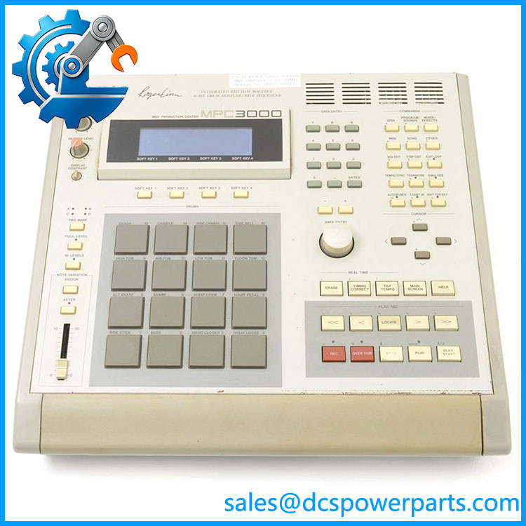
MPC3000-1A
Application Scenarios & Field Pitfalls — The Engineer’s Perspective
Engineering Pain Point
A motor protection relay must match the electrical measurement circuits and the intended protection scheme. A unit that powers up and communicates may still be unsuitable if its CT input rating, VT wiring, auxiliary supply, or configured protection functions differ from the original. Incorrect settings can cause nuisance trips or, more seriously, leave the motor inadequately protected.
Typical Applications
- Three-phase motor protection: Monitoring current, voltage, phase conditions, and thermal loading.
- Motor starter control: Implementing configured start/stop logic and interfacing with contactors or circuit breakers.
- Temperature-based protection: Monitoring compatible motor temperature sensors through the relay’s temperature inputs.
- Plant monitoring integration: Transmitting relay measurements and status over RS-485 Modbus where supported and correctly configured.
These applications reflect the published family capabilities; confirm the actual installed functions before relying on them for a particular motor.
Technical Pitfalls to Avoid
- Verify the exact variant. The
-1Asuffix is not decoded by the available product reference. Do not assume it means a 1 A CT input without confirmation from the nameplate or ordering documentation. - Match the CT secondary rating. Confirm whether the installed current transformers provide 1 A or 5 A secondary current. Check ratios, polarity, phase assignment, and earth-fault measurement arrangements before reconnecting the relay.
- Check voltage-transformer wiring. Confirm the voltage-input range, VT ratios, phase sequence, and grounding arrangement. Incorrect phase mapping can affect voltage-based protection and directional or sequence calculations where configured.
- Validate auxiliary power. The family lists more than one auxiliary-supply range. Identify the actual rating on the unit before applying power.
- Back up protection settings. Record motor full-load current, starting characteristics, thermal limits, earth-fault thresholds, voltage limits, and time delays before replacing the relay. Do not rely on factory defaults as an acceptable protection configuration.
- Check temperature sensor compatibility. Verify whether the installation uses RTD, PTC, or NTC sensors and confirm the relay configuration matches the actual sensor and wiring.
- Verify output logic and interlocks. Establish the function of each relay output and digital input before commissioning. Incorrect output mapping can affect start permissives, trip circuits, and breaker or contactor control.
- Test communications independently. For Modbus integration, verify the device address, baud rate, parity, register mapping, and supervisory-system scaling. Successful serial communication does not prove that all displayed measurements are correctly interpreted.
- Perform a documented protection test. Use an approved secondary-injection or functional-test procedure to verify the configured trip functions and output logic. Record the test conditions and results rather than relying solely on a successful power-up.
Related Products and Technical References
- — The base motor protection and control relay family associated with -1A. Use the official product information and technical manual to establish the variant’s capabilities.
- P&B MPR3000 — A related motor protection relay designation appearing in P&B’s product family and documentation. Confirm hardware and firmware differences before considering it as a substitute.
These references are provided for identification only. No direct replacement part number is confirmed for -1A.
Procurement Note
Before purchasing a P&B -1A, request clear photographs of the front label, side or rear nameplate, terminals, and any revision markings. Ask the supplier to disclose the actual condition—new, unused stored, repaired, or used—and provide a test report identifying which measurements, inputs, outputs, and protection functions were checked.
Confirm the following before installation:
- Full model code and the meaning of the
-1Asuffix. - Auxiliary-supply rating.
- CT and VT input configuration.
- Required temperature-sensor type.
- Relay output assignments and digital I/O mapping.
- Firmware and communication settings.
- Availability of configuration backups and commissioning records.
Engineering recommendation: Treat -1A as a configuration-specific protection relay. Confirm the suffix, electrical inputs, and programmed protection settings before approving it as a replacement.