Description
Product Overview
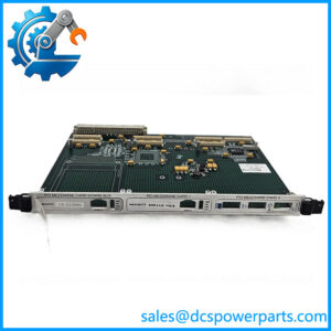
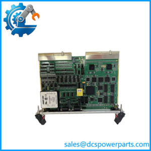
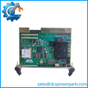
ThIS is a slave control module designed for the decentralized automation system used in marine and industrial equipment monitoring and control. Within the I/O assembly, it performs local processing duties, handles onboard signal interfaces, and coordinates supported plug-in modules. This arrangement distributes signal-processing work within the I/O station rather than requiring every field signal to be handled directly by the main controller. ThIS is therefore relevant to installations where established control hardware must remain compatible with the existing system architecture.
Its onboard configuration includes four digital inputs and four relay outputs with potential-free contacts, according to hardware documentation. The control processor also monitors internal supply voltages, including +5 V, +24 V, and ±15 V, and checks insulation relative to the module housing. Board-temperature monitoring provides an additional diagnostic input, including temperature information used for thermocouple reference-junction compensation. Up to six additional plug-in modules can be controlled through the card’s serial peripheral interface and associated selection logic, subject to the supported hardware arrangement.
For maintenance teams, the principal value of thIS lies in preserving the intended operation of an installed system without introducing an unverified hardware substitution. Typical evaluation points include the card revision, exact suffix, firmware requirements, connector arrangement, and compatibility with the existing I/O assembly. Marine engine monitoring, alarm panels, and distributed machinery control are relevant application areas for the wider platform. Before ordering a replacement, compare the installed card against the equipment documentation and inspect its revision marking; visually similar cards should not be assumed interchangeable.
Product Introduction (Non-Templated)
A failed slave processor can interrupt local signal handling even when the main control system remains operational. ThIS addresses this role within the control architecture, combining onboard digital signal interfaces with processing for supported expansion cards.
For an system upgrade or legacy replacement, verify the card revision, installed firmware, and I/O configuration before installation. Its documented support for up to six additional plug-in modules helps define the intended expansion scope.
Key Technical Specifications
| Parameter | Value |
|---|---|
| Product Model | SA653-1G |
| Manufacturer | NORIS Automation |
| Product Type | Slave CPU / control module |
| Product Series | N3000 |
| System Role | Local slave control processing |
| Onboard Digital Inputs | 4 |
| Onboard Relay Outputs | 4 |
| Relay Contact Type | Potential-free contacts |
| Additional Plug-in Modules | Up to 6, subject to configuration |
| Internal Voltage Monitoring | +5 V, +24 V, ±15 V |
| Temperature Monitoring | Onboard circuit-board temperature measurement |
| Communication Architecture | Serial SPI for supported plug-in modules |
| Installation Method | Installed within a compatible N3000 I/O assembly |
| Supply Voltage | System-level supply; confirm module-specific requirements |
| Operating Temperature | Verify against the applicable N3000 hardware revision |
| Firmware Compatibility | Must be checked against the installed N3000 configuration |
| Protection Rating | Depends on the complete assembly and installation |
| Condition | To be confirmed |
Technical note: The onboard I/O and expansion information comes from hardware documentation. Exact environmental ratings, revision-specific electrical limits, and firmware compatibility should be established from the applicable OEM documentation before commissioning.
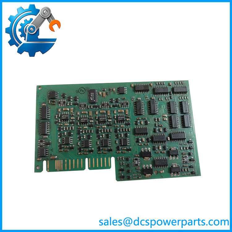
SA647-1G
Related Products
The following components belong to, or are documented for, the NORIS system. They serve different functions and should not be treated as direct replacements he .
-20G
An alternative slave CPU card variant. Confirm hardware revision, firmware, and application configuration before considering it as a replacement he .
SA647-1G
Universal analog input module for supported temperature sensors, resistance inputs, current signals, voltage signals, and contact signals. It complements the control module when analog measurement is required.
SA655-1G
Digital I/O expansion card with configurable input/output functions. Useful for expanding discrete signal handling where the installed configuration supports it.
SA655-2G
Related digital I/O variant. Verify its channel configuration and hardware revision against the required input/output function before substitution.
SA656-1G
Analog output amplifier supporting specified 0–2–10 V and 0–4–20 mA output ranges. Intended for compatible analog command signals rather than CPU processing.
SA648-1G
Associated power-unit component. Relevant when investigating supply distribution or a power-related fault affecting the I/O assembly.
SA650-21G
Master-side controller card referenced in system configurations. Its system role differs fhe slave control card.
-IMC
I/O master assembly used in distributed control configurations. It provides system-level context for the slave control and expansion cards.
Frequently Asked Questions (FAQ)
1. Can I replace aed without changing the entire I/O assembly?
Potentially, provided the replacement matches the installed hardware configuration.
Before installation:
- Confirm the complete model number and revision marking.
- Compare the connector arrangement and installed expansion cards.
- Verify the required firmware and application configuration.
- Record the existing settings and follow the OEM replacement procedure.
A matching model number alone does not guarantee that a replacement will operate correctly in every installation.
2. Can I hot-swap thIS while the system is running?
Do not assume hot-swapping is supported.
The available information does not establish the is designed for live removal or insertion. Interrupting its power or removing the card may affect local I/O processing and connected machinery functions.
Use the equipment’s approved shutdown and isolation procedure unless the applicable OEM documentation explicitly authorizes live replacement.
3. Dhe support firmware v3.1?
The exact firmware compatibilityhe with version 3.1 has not been verified.
Firmware compatibility can depend on the card revision, system software, and the installed master/slave configuration. Check the existing firmware identification and applicable release documentation before attempting an update or replacement. Do not assume that a firmware version used by another component applies to this card.
4. Will replache erase my control logic or configuration?
The answer depends on where the application logic and configuration data are stored.
he performs local slave processing, but the available documentation does not establish that all application logic is stored on this card or automatically transferred to its replacement.
- Back up the applicable system configuration before maintenance.
- Record firmware and revision details.
- Follow the documented restoration and commissioning procedure.
- Verify digital inputs, relay outputs, and connected expansion cards after replacement.
Do not rely on the replacement card to preserve the original configuration automatically.
5. Is a new-us guaranteed to be genuine and unused?
The term new surplus describes stock status; it does not, by itself, prove authenticity or operational condition.
For procurement acceptance, request:
- Photographs of the actual card and its model/revision markings.
- Confirmation of whether the unit is factory sealed or open stock.
- Inspection and functional-test records, where available.
- Written confirmation of the supplied condition and applicable warranty.
The actual unit’s condition must be confirmed before the product is represented as factory sealed or unused.
6. What should I checkhe reports a fault or the local I/O stops responding?
Start with the fault symptoms and the surrounding assembly rather than replacing cards at random.
- Power-related symptoms: Check the documented internal supply rails and the assembly’s power unit.
- Expansion-card faults: Verify the installed card types, connectors, and configuration.
- Digital signal faults: Check field wiring and the four onboard digital input and four relay output circuits.
- Intermittent behavior: Review temperature, grounding, insulation monitoring, and relevant fault records.
Follow the approved diagnostic procedure and isolate the equipment before working on field wiring.
7. What warranty applies to thIS replacement module?
Warranty coverage depends on the supplier’s written terms and the condition of the specific unit. The exact warranty period cannot be established from the model number alone.
Before placing an order, obtain written confirmation of the warranty duration, coverage for functional failures, return procedure, and any exclusions. For equipment used in marine machinery or other critical control applications, request the available inspection and test documentation as part of the procurement record.