Description
Key Technical Specifications
| Parameter | Specification |
|---|---|
| Product Model | PCS9100 |
| Manufacturer | Systeme Lauer GmbH |
| Product Family | PCSmaxi |
| Product Type | Modular graphic operator console |
| Display | Active LCD, full graphics |
| Resolution | 640 × 480 pixels |
| Operating Voltage | 24 VDC ±20% |
| Current Consumption | 650 mA without cassette; 1.15 A with four cassettes at 24 VDC |
| Maximum Inrush Current | 4 A at 32 VDC, with four cassettes |
| Internal Memory | Page ROM, 256 KB |
| Programming Interface | RS-232, 38.4 kbaud |
| Printer Interface | RS-232, 300–19,200 baud |
| External Keyboard Interface | RS-422, 130 kbaud |
| Additional Communication | RS-422/RS-485 through applicable interface configuration |
| Module Slots | Four rear slots |
| Count Inputs | Three; 19–33 VDC input range |
| Floating Output | Normally open contact, 0.5 A / 50 V resistive load |
| Backup Battery | 2.8 V, 1 Ah, replaceable |
| Operating Temperature | 0 to 45°C |
| Storage Temperature | -20 to +60°C |
| Front Protection | IP65 when installed in a panel |
| Rear Protection | IP20 |
| Dimensions | 410 × 266 × 75 mm, excluding connectors |
| Weight | Approximately 3.7 kg; 4.7 kg with four cassettes |
| Fuse | 3.15 A slow-blow |
These specifications are documented in the Lauer PCS 9000 / PCS 9100 PCSmaxi manual. Note that the actual communication and PLC interface configuration depends on the modules installed in the rear slots.
Product Introduction
LAUER PCS9100 PCSmaxi Operator Console
The LAUER PCS9100 is a modular industrial operator console featuring a 640 × 480 active LCD, numeric and alphanumeric keys, programmable function keys, and configurable soft-key functions. Its multitasking window system supports simultaneous display of machine information, messages, menus, recipes, and help screens.
Four rear module slots allow the hardware configuration to be adapted to the machine’s communication and expansion requirements. The unit uses 24 VDC power and supports serial programming through RS-232.
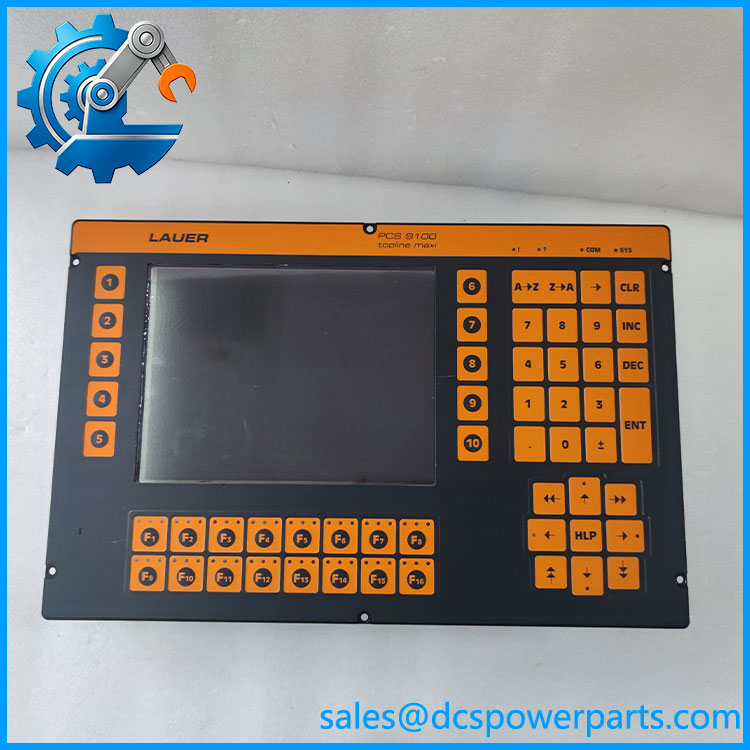
PCS9100
Application Scenarios & Field Pitfalls (Engineer’s Perspective)
Replacing a PCS9100 is not simply a matter of installing another display. The operating project, PLC interface cassette, communication wiring, and memory configuration all affect whether the machine can return to service.
Typical application scenarios
- Machine operator stations: Displays operating states, machine parameters, alarms, and operator menus.
- Production equipment: Supports recipe selection, parameter entry, and operating instructions.
- Packaging and process machinery: Provides programmable soft-key functions and multiple information windows.
- Legacy PLC installations: Communicates with programmable controllers through compatible interface modules installed in the rear slots.
Field pitfalls to check before replacement
1. PLC interface cassette: The PCS9100 requires an appropriate controller interface module. The manual identifies PCS 810 through PCS 830.3 modules for the Lauer protocol. Identify the installed cassette before ordering a replacement; the main console alone does not establish PLC compatibility.
2. Project recovery and programming: The PCS 9092 planning software is associated with the PCS9000/PCS9100 platform. Preserve the original .PCS project files, associated .INC files, firmware modules, and memory cassette contents. A replacement without the original application may power up but cannot reproduce the machine’s operating screens and logic interface.
3. Serial wiring and power: Verify RS-232 and RS-422/RS-485 pin assignments against the installed interface modules. The documented supply range is 24 VDC ±20%. Check the 3.15 A slow-blow fuse, battery condition, grounding, and power polarity before commissioning.
Related Products
| Model | Description | Relationship |
|---|---|---|
| PCS9000 | Lauer PCSmaxi operator console | Closely related console platform |
| PCS9092 | PCSmaxi project-planning software | Programming environment |
| PCS010 | Replacement backup battery | Listed for and related PCS models |
| PCS891 | Additional keyboard assembly for PCS9xx | Accessory for the PCS9xx family |
| PCS802 | Memory-pack interface referenced in the PCS891 accessory description | Related memory hardware |
| PCS810 | Lauer programmable-controller interface module | Controller interface family |
| PCS830.3 | Lauer programmable-controller interface module | Controller interface family |
| PCS920 | Lauer operator panel | Related legacy PCS family |
| PCS950 | Lauer operator panel | Related legacy PCS family |
These are family or accessory relationships, not a declaration of direct interchangeability. Confirm hardware revisions, installed modules, and software requirements before selecting a replacement.
Procurement and Quality Control Notes
The is a legacy Lauer platform. Historical technical references indicate that PCS9000/ models are no longer available as standard current-production products. Confirm repair and replacement support before planning a long-term maintenance strategy.
For procurement, request:
- Complete front and rear photographs.
- Confirmation of the four rear module positions and installed cassette part numbers.
- Display, keypad, and function-key operation test.
- Verification of RS-232 and controller communication.
- Backup battery and memory-retention condition.
- Confirmation that the original application can be loaded or retained.
Replacement warning: Do not approve a replacement based on model-family similarity alone. The installed controller interface module and original project files are critical to restoring machine operation.