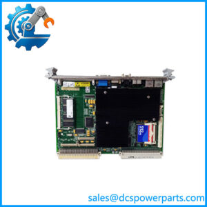
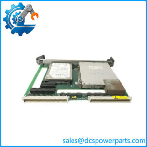
Description
Key Technical Specifications
| Parameter | Specification |
|---|---|
| Model | VMIVME-3125 |
| Standard assembly number | 332-003125-100, listed for a common configuration |
| Manufacturer | VMIC / GE Fanuc |
| Board format | 6U Eurocard |
| Bus architecture | VMEbus, ANSI/IEEE 1014-1987 |
| ADC resolution | 12 bit |
| Input capacity | 32 single-ended or 16 differential channels |
| Aggregate conversion rate | 40 kHz |
| Programmable gain | ×1, ×10, ×100 |
| Voltage input ranges | ±5 V, ±10 V, 0 to +10 V; additional ranges available with gain selection |
| Current input ranges | Configuration-dependent; documented options include 0–20 mA, 4–20 mA, and 5–25 mA |
| Data storage | Dual-ported data registers |
| Scanning mode | Continuous automatic scanning |
| Input filtering | Standard 50 kHz low-pass filter; optional 40 Hz filter for voltage-input configurations |
| Current-input options | 250 Ω or 500 Ω precision termination, depending on ordering configuration |
| Ground isolation | 1,000 VDC analog-ground to digital-ground isolation |
| Built-in test | Yes |
| VMEbus address space | 128 bytes in short I/O (A16) space |
| Front-panel connector | 37-pin D-sub female connector |
| Power requirements | Confirm the required backplane supply and current from the applicable manual |
| Operating temperature | Confirm the rating for the exact ordering configuration |
Specifications are based primarily on the VMIC technical datasheet and board manual. Input ranges, filter selection, and current-input termination depend on the ordering configuration.
Major Features and Advantages
Continuous analog acquisition: The VMIVME-3125 scans and converts configured input channels automatically, with an aggregate conversion rate of 40,000 samples per second. Converted readings remain available through dual-ported data registers, reducing the need for the host processor to initiate each conversion individually.
Flexible channel configuration: The board supports 32 single-ended or 16 differential voltage inputs. Single-ended wiring can suit signals sharing a common reference, while differential wiring can help address certain common-mode noise and grounding issues. The correct configuration depends on the field signal and system grounding design.
Selectable gain and measurement ranges: Hardware-selectable gains of ×1, ×10, and ×100 allow the input stage to accommodate different signal amplitudes. The available A/D ranges include ±5 V, ±10 V, and 0 to +10 V, with smaller effective ranges available through gain selection. The gain and range settings must match the connected signal to prevent clipping or incorrect scaling.
Filtering and current-input options: The standard voltage-input configuration uses a 50 kHz low-pass filter, with an optional 40 Hz filter. Specified current-input configurations use precision termination resistors. Confirm the exact ordering code before assuming that a particular filter or current-input option is installed.
Built-in diagnostics: The built-in-test function applies an internal reference voltage to the programmable-gain amplifier, allowing the acquisition path and associated control logic to be checked. This supports maintenance diagnostics, but it does not replace testing with suitable external signals when validating the complete measurement chain.
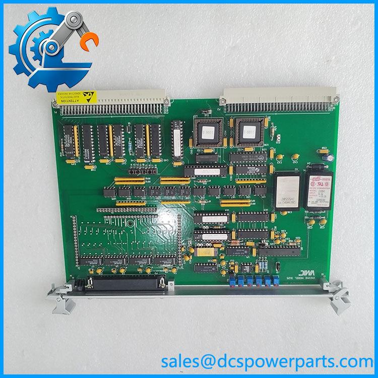
VMIVME-3125
Application Scenarios and Common Pain Points
The VMIVME-3125 is intended for systems that need repeated analog measurements through a VMEbus host.
- Industrial process monitoring: Acquire analog measurements from compatible transmitters and instrumentation.
- Test and measurement systems: Collect multiple voltage or current signals for analysis by a VMEbus computer.
- Factory automation: Supply digitized field measurements to legacy control applications.
- Equipment refurbishment: Replace a failed acquisition board while retaining the existing VMEbus architecture and host software.
Field consideration: Incorrect gain jumpers, input-mode selection, or address configuration can cause inaccurate readings or prevent the host from accessing the board. Record the original settings before removal.
Related GE Fanuc / VMIC Products
| Model | General function |
|---|---|
| VMIVME-3123 | 16-channel, 16-bit high-throughput analog input board with simultaneous sampling |
| VMIVME-3126 | Related analog acquisition board family; verify exact variant |
| VMIVME-4140 | Analog output board with 32 channels and 12-bit resolution |
| VMIVME-4514A | 16-channel scanning analog input board |
| VMIVME-2536 | 32-channel optically coupled digital I/O module |
| VMIVME-7750 | VMEbus single-board computer |
These products have different measurement architectures or functions. In particular, the VMIVME-3123 uses 16-bit conversion with simultaneous sampling, unlike the VMIVME-3125’s 12-bit scanning architecture. They are reference points for system planning, not direct substitutes.
Engineer’s Guide: Before Ordering or Installation
1. Confirm the ordering configuration. Check the full model and assembly number, including any suffix that specifies input, filtering, or termination options.
2. Match the electrical setup. Record whether the original board uses single-ended or differential inputs, the gain setting, voltage or current range, and the filter configuration. Confirm that the field wiring matches the replacement.
3. Verify the VMEbus configuration. Check the address jumpers, address modifier settings, backplane supply requirements, and host software assumptions against the manual.
Safety note: Power down the chassis before removing or installing the board unless the system documentation explicitly permits otherwise. Use appropriate ESD precautions and validate readings with known input signals after installation.
Frequently Asked Questions
What is the GE Fanuc VMIVME-3125 used for?
It is a 12-bit analog-to-digital converter board used to collect analog signals in VMEbus-based data acquisition, instrumentation, and process-control systems.
How many input channels does the VMIVME-3125 support?
It supports 32 single-ended or 16 differential voltage-input channels. The board’s input configuration must be set to match the wiring arrangement.
What is the sampling rate of the ?
The documented aggregate conversion rate is 40,000 samples per second. This is the aggregate rate across the scanning system, not 40 kHz per channel.
Does the accept 4–20 mA signals?
A current-input configuration is documented, including a 4–20 mA range. Confirm that the specific board has the appropriate input option and termination configuration before connecting current-loop signals.
What should be checked if the board reports incorrect readings?
Verify the input wiring, channel mode, gain selection, input range, grounding, filter option, and host data interpretation. If readings remain incorrect, consult the manual’s built-in-test and troubleshooting procedures.
Can the replace the VMIVME-3123?
Not as a direct functional substitute without redesign or software changes. The VMIVME-3123 is a 16-bit simultaneous-sampling board, while the is a 12-bit scanning ADC board. Their timing, resolution, and acquisition behavior differ.
What should buyers verify when sourcing a replacement?
Confirm the complete model and assembly number, installed options, jumper configuration, physical condition, test evidence, warranty terms, and lead time. For refurbished units, request documented testing of multiple input channels, gain settings, and the VMEbus interface.
Recommended product listing title: GE Fanuc 12-Bit 32-Channel VMEbus Analog Input Board