Description
Product Introduction
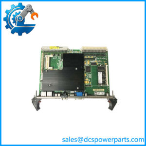
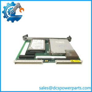
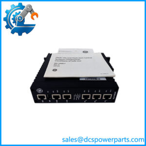
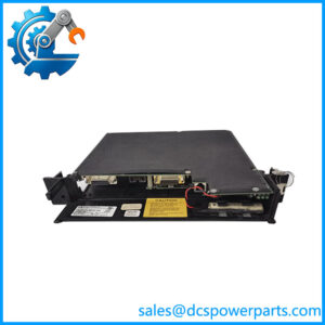
The GE IS200TRTDH1DCB is a TRTD RTD input terminal board used in GE Speedtronic Mark VI turbine-control systems. Its function is to provide the field termination and signal-conditioning interface for resistance temperature detectors used to measure temperatures throughout a turbine-generator installation. GE Mark VI systems use dedicated RTD interface hardware rather than connecting RTD field wiring directly to a general-purpose analog input module.
The IS200TRTDH1DCB accepts 16 three-wire RTD inputs through two barrier-style terminal blocks. Each block provides eight RTD channels, and the board incorporates input noise suppression to reduce the effect of high-frequency interference and electrical transients. Two 37-pin connectors, identified as JA1 and JB1, provide the interface to the associated PRTD electronics.
The IS200TRTDH1DCB belongs to the H1D configuration of the TRTD family. Available technical references describe this version as a simplex board with two DC-type connections for the PRTD and normal-scan arrangement. When sourcing a replacement, the complete IS200TRTDH1DCB number should be matched because other TRTD versions have different redundancy and interface arrangements.
Technical Specifications
| Parameter | Specification |
|---|---|
| Manufacturer | General Electric |
| Model | IS200TRTDH1DCB |
| Functional Acronym | TRTD |
| Product Type | RTD Input / Termination Board |
| System | GE Mark VI / Mark VIe |
| Application | Turbine temperature measurement |
| RTD Inputs | 16 |
| Input Wiring | 3-wire RTD |
| Channels per Terminal Block | 8 |
| Terminal Blocks | 2 |
| RTD Excitation | Approx. 10 mA DC, multiplexed |
| Supported RTDs | Pt 10/100/200 Ω, Cu 10 Ω, Ni 120 Ω |
| Measurement Span | Approx. 0.3532–4.054 V |
| Maximum Lead Resistance | 15 Ω, two-way |
| PRTD Connection | 2 × 37-pin connectors |
| Connector Designations | JA1, JB1 |
| Input Protection | Noise suppression / surge protection |
| Hardware Configuration | Simplex H1D |
| Installation | Mark VI/Mark VIe turbine-control cabinet |
The documented TRTD family specifications include the 10 mA multiplexed excitation, supported RTD types, 15 Ω maximum two-way lead resistance, and 0.3532–4.054 V signal span.
Main Features and Engineering Considerations
16-Channel RTD Interface
The IS200TRTDH1DCB provides sixteen RTD channels using three-wire field connections. Two removable terminal blocks make field maintenance more practical, with eight RTD inputs assigned to each block.
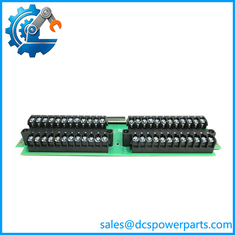
IS200TRTDH1DCB
Multiplexed RTD Excitation
The TRTD architecture supplies approximately 10 mA DC excitation to the connected RTDs on a multiplexed basis. The resulting resistance-dependent voltage is passed to the PRTD electronics for conversion into temperature information for the turbine controller.
RTD Type Flexibility
The documented hardware supports several resistance-temperature characteristics, including 10, 100, and 200 Ω platinum, 10 Ω copper, and 120 Ω nickel RTDs. Software linearization is used to convert the measured resistance into temperature values.
Noise and Surge Suppression
Each input includes noise-suppression circuitry intended to reduce high-frequency interference and transient effects. This is particularly relevant in turbine cabinets where RTD wiring can run near excitation, switching, and power-control circuits.
Application Scenarios
The is used in:
- GE Mark VI turbine control
- GE Mark VIe installations
- Gas turbine temperature monitoring
- Steam turbine temperature monitoring
- Generator temperature measurement
- Bearing temperature monitoring
- Winding and equipment temperature measurement
- Turbine auxiliary systems
- Industrial power-generation plants
A public industrial procurement catalog also identifies the IS200TRTDH1D as an RTD termination board for Mark VIe, confirming its use in turbine-control applications.
Engineer’s Guide: Field Pitfalls
⚠️ Do not confuse H1D with other TRTD versions.
The TRTD family contains multiple hardware configurations, including simplex and redundant variants. The H1DCB suffix should be matched exactly.
⚠️ Verify the PRTD interface.
The board uses JA1 and JB1 37-pin connectors to interface with the associated PRTD electronics. Connector condition and cable routing should be checked during replacement.
⚠️ Check three-wire RTD wiring.
Incorrect lead compensation or a loose third wire can produce temperature errors even when the terminal board itself is healthy.
⚠️ Check lead resistance.
The documented maximum two-way cable resistance is approximately 15 Ω. Excessive cable resistance can affect measurement accuracy.
⚠️ Do not diagnose every RTD fault as a board failure.
Open sensors, shorted sensors, damaged field cables, shield problems, and connector faults can all produce abnormal temperature readings.
⚠️ Test the complete measurement chain.
A meaningful replacement test should verify the RTD input, terminal connections, PRTD interface, temperature conversion, diagnostics, and controller indication.
Frequently Asked Questions
It is a TRTD RTD input/termination board used in GE Mark VI/Mark VIe turbine-control systems.
How many RTDs can it handle?
The TRTD H1D configuration supports 16 three-wire RTD inputs, arranged as eight channels on each of two terminal blocks.
What RTD types are supported?
The documented types include Pt 10/100/200 Ω, Cu 10 Ω, and Ni 120 Ω.
What is the difference between TRTD and PRTD?
The TRTD is the field termination/interface board, while the associated PRTD electronics perform the RTD signal processing and conversion.
Is a standalone temperature transmitter?
No. It is a turbine-control RTD interface/termination board and depends on the associated Mark VI/Mark VIe I/O architecture.
What should be verified before purchasing?
- Complete board revision
- TRTD H1D configuration
- 16-channel requirement
- PRTD compatibility
- JA1/JB1 connector configuration
- RTD type
- Three-wire field wiring
- Cable resistance
- Terminal-block condition
- Input diagnostic test
- Temperature-loop functional test
Procurement note: For a used or refurbished , I would request clear photographs of the full board label, revision markings, terminal blocks, and JA1/JB1 connectors, plus evidence that all RTD channels have been tested. A simple continuity or power-on test does not adequately demonstrate temperature-measurement performance.