Description
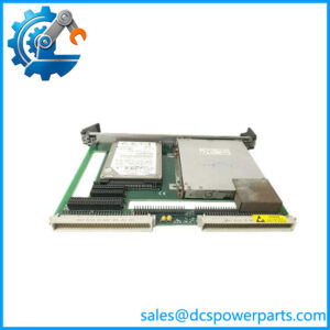
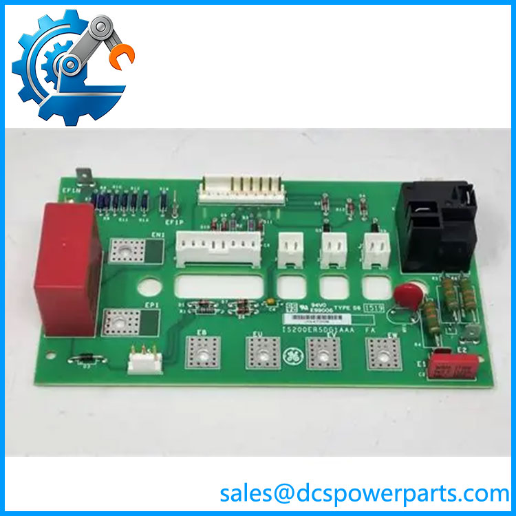
GE IS200ERSCG1A | EX2100 Exciter Regulator Static Converter
Key Technical Specifications
| Parameter | Specification |
|---|---|
| Product Model | IS200ERSCG1A |
| Full Ordering Reference | IS200ERSCG1AAA |
| Manufacturer | GE |
| Product Family | EX2100 Excitation Control |
| Board Type | Exciter Regulator Static Converter |
| Functional Acronym | ERSC |
| Group | G1 |
| Application | Generator excitation / regulator power conversion |
| Output Type | PWM DC excitation output |
| Maximum Continuous Output | 250 VDC / 35 A |
| 10-Second Output Capability | 250 VDC / 52.5 A |
| Power Switching Device | IGBT module |
| Associated Boards | ERDD, ERRR |
| Application Architecture | Simplex |
| Approximate Board Size | 4 × 6 in. |
| IGBT Connections | 12 soldered gate connections + 4 bolted power connections |
| Voltage Feedback | On-board voltage attenuator |
| Mounting | Vertical heat-sink arrangement for IGBT |
| Revision | A |
The published technical records identify the ERSC as the static power-conversion element of the EX2100 excitation system. The IGBT module is mechanically mounted to a heat sink and electrically connected through dedicated gate and power connections.
Product Introduction
The GE IS200ERSCG1A is an Exciter Regulator Static Converter (ERSC) board used in GE EX2100 excitation control systems. Its primary job is to provide the regulator’s PWM DC output for excitation-field control while interfacing the DC source, generator field circuit, dynamic-discharge circuitry, and regulator relay circuitry. The board therefore sits in the power-conversion portion of the excitation system rather than acting as a conventional Mark VI processor or general-purpose I/O board.
The board uses an IGBT power module for static switching and includes voltage-sensing circuitry for monitoring the excitation field. The ERSC also interfaces with the IS200ERDD dynamic discharge board and IS200ERRR exciter regulator redundant relay board. The G1 version is associated with simplex regulator arrangements, so the system architecture must be checked before treating another ERSC variant as an equivalent replacement.
IS200ERSCG1A
Application Scenarios & Field Pitfalls — The Engineer’s Perspective
Engineering Pain Point
The main replacement risk with the IS200ERSCG1A is confusing a board-level part replacement with a complete excitation-regulator replacement. This board handles substantial excitation power and contains the IGBT switching stage, so failure analysis needs to consider the associated field circuit, DC source, gate-drive signals, discharge path, heat-sink condition, and regulator control signals. Simply installing another board without checking the cause of the original failure can result in another IGBT or board failure during commissioning.
Typical Applications
- Generator excitation control on GE EX2100 systems.
- Static DC excitation regulation for steam, gas, and hydro turbine-generator applications.
- PWM field-current control within the EX2100 Power Conversion Module.
- Simplex excitation regulator configurations requiring ERSCG1 hardware.
Technical Pitfalls to Avoid
- Verify G1 versus G2 architecture. ERSCG1 is associated with simplex operation. ERSCG2 includes an additional field-discharge path for regulator transfer in redundant configurations. These are not interchangeable solely because both carry the ERSC designation.
- Inspect the IGBT circuit before replacement. The IGBT module is directly integrated with the ERSC board through soldered gate leads and bolted power connections. A failed gate-drive circuit, abnormal field load, shorted field circuit, or cooling problem can damage a replacement board.
- Check the field-discharge path. The ERSC works with the ERDD and ERRR boards. A problem elsewhere in this circuit can appear as an ERSC failure even when the static converter board itself is not the original fault.
- Do not treat 250 VDC / 35 A as a universal operating point. These are published maximum capabilities, not necessarily the configured operating point of the installed excitation system. Generator field rating, regulator configuration, thermal conditions, and system design must be checked separately.
- Inspect mechanical mounting and heat transfer. The IGBT is mounted vertically against a dedicated heat sink. Poor thermal contact, damaged mounting hardware, or contamination around the power section can become a reliability problem after board replacement.
- Confirm the complete identification. Records commonly associate IS200ERSCG1A with IS200ERSCG1AAA. Before procurement, compare the board artwork, revision, connector arrangement, and installed system documentation rather than relying only on the shorter IS200 number.
Related Products
- GE IS200ERDDG1A — dynamic discharge board. It works with the ERSC circuitry during excitation-field discharge and should be considered when troubleshooting the complete power-conversion path.
- GE IS200ERRRH1A — Exciter regulator redundant relay board associated with the ERSC/ regulator architecture.
- GE IS200ESYSH1A — Exciter control card used within the control system; its function is different from the ERSC power-converter stage.
- GE IS200EROCH1A — exciter regulator option card, providing a different control/interface function from the ERSC.
- GE IS200ERAXH1A — Auxiliary regulator control/excitation I/O board; not a substitute for the ERSC power-conversion stage.
- GE IS200EPDMG1B — /Mark VIe exciter power distribution module; it belongs to the excitation power-distribution side rather than the ERSC switching stage.
- GE IS200ERGTH1A — regulator ground detector card, serving a monitoring/protection function rather than DC power conversion.
- GE IS200EXCSG1A — conduction sensor card; its sensing function is distinct from the ERSC converter.
Procurement and Replacement Note
For an IS200ERSCG1A replacement, the minimum verification set should include the complete board identifier, artwork/revision, cabinet configuration, simplex versus redundant architecture, ERDD/ERRR arrangement, IGBT/power-section condition, field voltage/current requirements, and existing regulator parameters.
The most important point is that this is a power-conversion board, not a standard low-level control PCB. The documented 250 VDC and 35 A continuous capability places the ERSC directly in the excitation power path. If the original board failed catastrophically, inspect the field circuit, IGBT gate-drive path, discharge circuit, and cooling interface before commissioning the replacement.