Description
GE IS200EDISG1AAA Exciter Power Distribution Board
Product Introduction
The GE IS200EDISG1AAA is an EDIS Exciter Power Distribution Board used in GE EX2100e thyristor-based excitation-control systems. Its job is fundamentally different from that of the excitation processor or bridge-control boards: EDIS provides the internal power-distribution path that connects customer-supplied AC and DC control power to the electronic hardware of the excitation system. Technical records identify the EDIS as an EX2100e Power Distribution Board and describe its role in supplying controllers, bridge-interface boards, and I/O modules.
The GE IS200EDISG1AAA can accept 125 VDC control power and, in the documented EX2100e arrangement, customer AC sources of 115 VAC or 220 VAC at 50/60 Hz. AC power is handled through the associated DACA power-conversion architecture before being distributed to the system electronics. This makes the EDIS a central power-path component in the excitation cabinet rather than a conventional communication or PLC I/O card.
For the GE IS200EDISG1AAA, procurement should focus on the complete excitation-system configuration rather than treating the board as a generic power-distribution PCB. The exact AC/DC source arrangement, DACA configuration, connected EX2100e hardware, terminal wiring, protection devices, and board revision all matter. The full IS200EDISG1AAA identifier should be matched during replacement. Supporting records also identify the board as legacy/obsolete hardware, which makes condition assessment and functional testing particularly important for installed EX2100e systems.
Technical Specifications
| Parameter | Specification |
|---|---|
| Product Model | IS200EDISG1AAA |
| Manufacturer | General Electric |
| Functional Acronym | EDIS |
| Product Type | Exciter Power Distribution Board |
| Excitation System | EX2100 / EX2100e |
| Control Architecture | Thyristor-based digital excitation control |
| DC Input | 125 VDC |
| AC Input | 115 VAC / 220 VAC, 50/60 Hz |
| Number of AC Sources | Up to 2 in the documented configuration |
| Auxiliary Supply | 28 VDC identified in supporting records |
| AC Conversion | Associated DACA power-conversion boards |
| Primary Function | Internal excitation-system power distribution |
| Connected Hardware | Controllers, bridge-interface boards, I/O and auxiliary excitation modules |
| Communication | Not a standalone Ethernet/fieldbus communication board |
| Mounting | EX2100e excitation-system cabinet/rack assembly |
| Functional Revision | G1 |
| Artwork / Assembly Suffix | AAA |
| Environmental Data | Supporting records report -30 to +65°C operating; verify against the applicable GE system manual before publication as an installation limit |
| Manual References | GEA-S1302A; GEI-100777 |
| Lifecycle | Legacy / obsolete |
Specification caution: the 125 VDC and 115/220 VAC input values are supported by multiple technical records. The exact permissible source combinations, fuse ratings, branch-current limits, and DACA output characteristics should be taken from the cabinet-specific drawings and applicable GE manual rather than inferred from the board number.
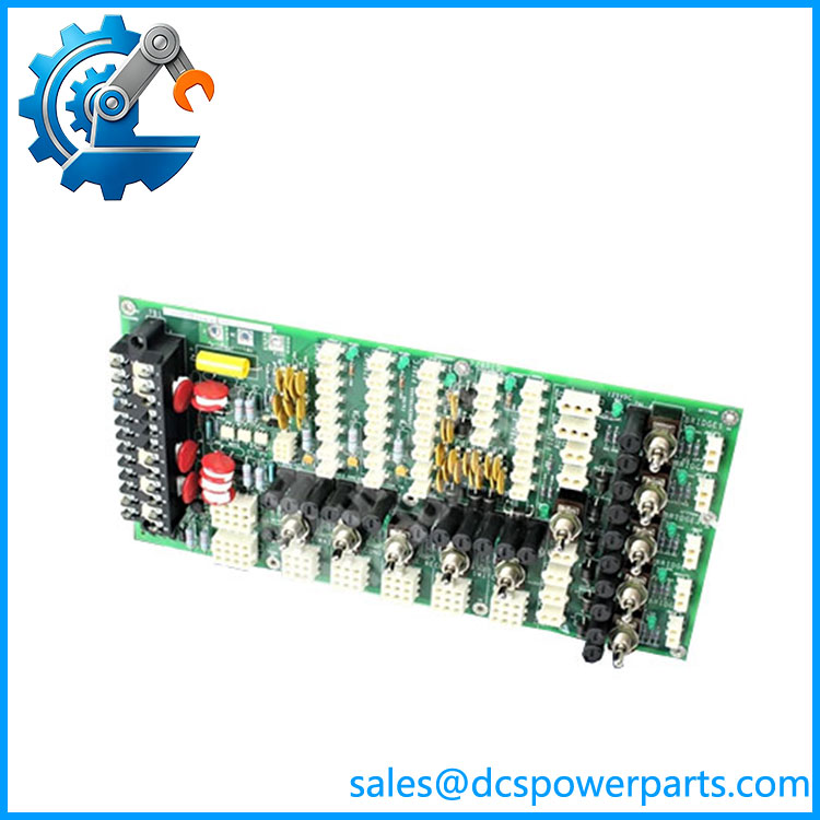
IS200EDISG1AAA
Main Features and Engineering Considerations
1. Centralized Excitation Power Distribution
The provides the power-distribution infrastructure for the EX2100e excitation-control cabinet. It interfaces customer control-power sources with the electronic subsystems that perform excitation regulation, feedback acquisition, bridge control, auxiliary control, and system communications.
2. AC and DC Source Compatibility
The documented EX2100e arrangement can use 125 VDC and AC control-power sources. Records describe up to two 115 VAC or 220 VAC, 50/60 Hz supplies. This arrangement is important for systems where station battery power and AC auxiliary power are both part of the excitation-power design.
3. Relationship with DACA
The EDIS should not be evaluated independently from the associated DACA hardware. In the documented architecture, AC input power is rectified by DACA hardware and then made available to the excitation-system power-distribution path. A replacement EDIS therefore needs to be checked against the installed DACA configuration.
4. Feeds Multiple Excitation Subsystems
The EDIS power path can support a range of EX2100e hardware, including the universal controller, high-speed serial-link hardware, auxiliary interface equipment, bridge interface equipment, AC feedback, DC feedback, and de-excitation circuitry.
5. Not a Communication Controller
Some online listings incorrectly associate unrelated Ethernet functions with this part number. The should be classified as an Exciter Power Distribution Board, not an embedded Ethernet interface or PLC communication processor. The HSSL mentioned in EX2100e documentation is part of the overall control architecture; it should not be interpreted as making EDIS itself an Ethernet communications card.
6. Revision Control Is Important
The full designation should be recorded from the actual PCB label. The IS200 family uses multiple revision and artwork identifiers, and supporting records distinguish the G1 functional family from the later suffix characters. Do not approve a visually similar EDIS board without comparing the complete identifier and system documentation.
Application Scenarios
- GE EX2100e generator excitation systems
- Gas turbine-generator excitation cabinets
- Steam turbine-generator excitation systems
- Thyristor excitation control
- Generator field-power control infrastructure
- AC/DC control-power distribution
- EX2100e controller power distribution
- Excitation bridge interface power supply
- Existing GE Speedtronic system maintenance
- Legacy EX2100e retrofit and spare-parts programs
Engineer’s Guide: Field Pitfalls
Do not confuse EDIS with the excitation controller.
The EDIS distributes power. It is not the primary processor responsible for excitation regulation.
Verify the incoming power arrangement.
The documented system can involve 125 VDC and one or two AC sources. Confirm the actual cabinet wiring before energizing a replacement.
Check the DACA boards.
If the AC-to-DC conversion path has a fault, replacing EDIS alone may not correct the underlying problem.
Record fuse and switch conditions.
EDIS power-distribution assemblies can involve multiple branch circuits. A failed branch should be investigated before installing another board; otherwise a downstream short or overload can damage the replacement.
Do not assume all IS200EDISG1A variants are interchangeable.
The complete catalog number and revision should be compared with the installed board and system drawings.
Use appropriate electrical isolation procedures.
This board can be connected to both high-energy DC and AC control-power sources. The presence of a PCB does not make it a low-voltage maintenance component.
Inspect connector and terminal condition.
Heat discoloration, loose terminals, oxidized contacts, and damaged connectors can produce intermittent power faults that appear to originate from EDIS itself.
Test the board as part of the excitation system.
A meaningful replacement test should verify incoming AC/DC power paths and downstream branch outputs under the appropriate controlled load. A visual inspection alone is not sufficient for a critical excitation-system spare.
Frequently Asked Questions
What is GE ?
It is an EDIS Exciter Power Distribution Board used in GE EX2100e excitation-control systems.
What does EDIS stand for?
EDIS refers to the Exciter Power Distribution function within the EX2100e excitation architecture.
What voltage does use?
Technical records identify 125 VDC and AC input arrangements of 115 VAC or 220 VAC at 50/60 Hz, depending on the installed system configuration.
Is an I/O module?
No. It is a power-distribution board rather than a conventional analog or digital I/O module.
Does communicate over Ethernet?
It should not be classified as an Ethernet communication board. Its principal function is excitation-system power distribution.
What equipment works with the EDIS board?
The EDIS power architecture can supply various EX2100e control and interface hardware, including controller, HSSL, auxiliary-interface, bridge-interface, feedback, and de-excitation components.
Is obsolete?
Available technical records classify this IS200 hardware as a legacy/obsolete product family.
What should be verified before buying a replacement?
Verify the complete part number, functional/artwork revision, incoming AC/DC power arrangement, DACA configuration, terminal wiring, downstream branch loads, and condition of the associated EX2100e hardware.
Procurement Note
For a replacement , request a clear PCB label photograph and compare it against the installed EDIS before purchase. The critical checks are full part-number matching, revision identification, AC/DC input configuration, DACA compatibility, terminal condition, fuse/branch arrangement, and functional power-distribution testing.
For a used or refurbished board, I would want evidence that the AC and 125 VDC input paths and downstream distribution circuits were actually tested. A board that merely powers up on a bench is not necessarily equivalent to one that has been tested under the relevant EX2100e load conditions.