Description
Key Technical Specifications
| Parameter | Specification |
|---|---|
| Manufacturer | GE Fanuc |
| Part Number | IC670ALG310-JA |
| Base Module | IC670ALG310 |
| Product Family | Genius Field Control |
| Product Type | 8-Point Isolated Analog Voltage-Source Output |
| Number of Outputs | 8 single-ended channels |
| Isolation Arrangement | 2 isolated groups of 4 channels |
| Output Range | -10 to +10 VDC |
| Alternate Range | 0 to +10 VDC |
| Output Overrange | Approximately ±10.25 V |
| Resolution | 14-bit |
| Accuracy | 0.25% of full scale maximum over operating temperature; 0.15% at 25°C |
| Minimum Load | 5 kΩ |
| Maximum Load Capacitance | 1 µF |
| Update Time | Approximately 1.5 ms typical |
| External Supply | 18–30 VDC, 24 VDC typical |
| Backplane Current | 170 mA maximum |
| External Supply Current | 275 mA maximum at 18 V, all outputs at -10 V into minimum load |
| Operating Temperature | 0°C to +55°C ambient |
| Ground/Logic Isolation | 1500 VAC peak for 1 minute; 250 VAC continuous |
| Diagnostics | Underrange, overrange, calibration, power-supply, BIU timeout and configuration-related diagnostics |
| Configuration | Through Genius BIU / compatible Hand-held Monitor |
| BIU Compatibility | Genius BIUs revision 2.0 or later |
The manufacturer’s manual identifies the IC670ALG310 as an eight-channel isolated voltage-source output module with two groups of four outputs. The specified hardware output range is -10.25 to +10.25 V, while normal configured ranges are ±10 V and 0 to +10 V.
One important correction for procurement: some secondary listings incorrectly describe this module as a 4–20 mA/current output device or place it in newer PACSystem families. The engineering documentation identifies it as a Genius Field Control voltage-output module, not a conventional current-output card.
Application Scenarios & Pain Points
Analog output failures tend to show up at the process level. The controller may report healthy communications while a final-control element simply stops responding to its reference signal. That makes a proper output simulation test particularly valuable.
- Valve and actuator control: The 0–10 V or ±10 V signal can be used where the controlled device accepts a voltage reference.
- Drive and speed references: Suitable for equipment requiring an analog voltage command, provided the receiving device’s input impedance and signal range match the configured output.
- Process control loops: Individual channel scaling allows the raw digital value to be converted into application-specific engineering units.
- Legacy Genius Field Control stations: The module fits existing Genius distributed I/O architectures and communicates through the Field Bus Interface Unit rather than directly through a modern Ethernet PLC backplane.
Brief Field Case
A useful troubleshooting sequence on an old Genius station is to measure the module’s external supply first, then check the BIU status, and finally force a known output value. If the commanded value changes in the PLC but the field voltage does not, the fault can be narrowed much faster than replacing the entire Genius station.
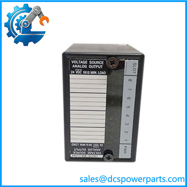
IC670ALG310-JA
Related Products
- GE Fanuc IC670ALG310-JA — The subject module; eight isolated analog voltage outputs with configurable scaling and 14-bit resolution.
- GE Fanuc IC670ALG310 — Base module designation for the IC670ALG310-JA version. Documentation generally describes the functional module without the JA suffix.
- GE Fanuc IC670CHS002 — Genius Field Control terminal/base hardware used to provide field wiring connections for compatible modules. It is complementary hardware, not an analog output replacement.
- GE Fanuc IC670GBI002 — Genius Bus Interface Unit family hardware used as the communication interface between the Genius bus and Field Control I/O. The BIU is a required architectural component rather than a substitute for ALG310.
- GE Fanuc IC670GBI001 — Earlier Genius BIU variant. When working with , check BIU revision because the module requires a compatible revision 2.0 or later BIU.
- GE Fanuc IC670ALG230 — Related Genius analog I/O hardware from the same broader Field Control family, but with a different signal function. It should not be assumed to have the same output characteristics.
- GE Fanuc IC670ALG630 — Thermocouple analog input module. It complements analog output applications but handles temperature input rather than voltage output.
- GE Fanuc IC670MDL-series modules — Digital Field Control I/O modules. These can share the Genius architecture but provide discrete rather than continuous analog signals.
- GE Fanuc IC670TBM-series terminal hardware — Field wiring accessories associated with Genius Field Control installations. Exact terminal compatibility should be checked against the module and station configuration.
The Engineer’s Guide: Field Pitfalls to Avoid
WARNING 1 — Do not confuse voltage output with 4–20 mA output.
is specifically an analog voltage-source output module. The normal ranges are ±10 V and 0–10 V.
How to avoid it: Check the receiving device’s input specification before wiring. A 4–20 mA input cannot simply be connected to this module because both are called “analog output.”
WARNING 2 — Check the Genius BIU revision.
The is documented as compatible with Genius Field Bus Interface Units revision 2.0 or later.
How to avoid it: Record the BIU model and revision before ordering the replacement. Do not assume an old-looking BIU is automatically compatible.
WARNING 3 — Remember the separate field power supply.
The module requires an external 18–30 VDC source for its output circuitry. The backplane/BIU supply and the user/output supply are not the same thing.
How to avoid it: When diagnosing a dead output, measure the external user supply at the module terminals before condemning the card.
Frequently Asked Questions (FAQ)
What is GE Fanuc -JA?
It is an 8-channel isolated analog voltage output module in the Genius Field Control I/O family. It converts digital output data from the Genius BIU into configurable analog voltage signals.
The module is intended for applications requiring voltage references rather than direct digital switching or 4–20 mA current output.
What voltage ranges does -JA support?
The two standard configured ranges are:
- -10 to +10 VDC
- 0 to +10 VDC
The hardware provides approximately ±10.25 V of output capability beyond the nominal configured range.
Each channel can have its own scaling parameters.
How many channels does -JA have?
It has eight single-ended analog voltage outputs, organized into two isolated groups of four.
This grouping matters during wiring because the isolation is not necessarily channel-to-channel across all eight outputs.
What power supply does -JA require?
The documented external supply range is 18–30 VDC, with 24 VDC as the typical value. Maximum external supply current is specified at 275 mA under the stated worst-case condition. The module also draws up to 170 mA from the BIU power supply.
If all channels are dead, check this supply before replacing the module.
be used with an old Genius Field Control station?
Yes, provided the station contains a compatible Genius BIU. The documentation specifically states compatibility with BIUs revision 2.0 or later.
The module is configured through the BIU using a compatible Hand-held Monitor, so the existing station configuration should be documented before replacement.
obsolete?
The family is a legacy GE Fanuc/Field Control product, and current secondary catalogs identify it as discontinued.
That does not make an existing module unusable. It does mean that for plant maintenance, an electrically tested spare is worth keeping on the shelf—especially where the Genius station is still supporting production equipment.
What should I request when buying a r?
For a critical spare, request:
- Exact nameplate photograph.
- Front and rear photographs.
- Output-channel functional test.
- Verification of both ±10 V and 0–10 V operating ranges.
- External power-supply test.
- BIU communication/configuration test.
- Diagnostic LED verification.
- Confirmation of the terminal/base assembly.
- Hardware revision information.
- Written warranty and condition statement.
For a refurbished unit, I would specifically ask for a measured output test on all eight channels. A card that simply powers up is not enough; an analog output module can look perfectly healthy while one channel has a damaged output stage.