Description
GE DS200TCCAG1BAA
Product Introduction
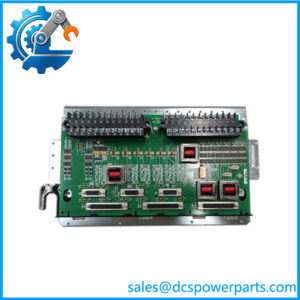
GE DS200TCCAG1BAA is a TCCA TC2000 Analog I/O Board used within the legacy GE Mark V Speedtronic turbine control platform. Unlike a passive termination board, this assembly contains an 80196 microprocessor, PROM devices, programmable logic, status indication, and dedicated internal signal interfaces. Its role is to process and exchange analog-related control information between the Mark V control architecture and field termination circuitry. The board is associated with Mark V turbine systems used for gas, steam, and other compatible turbine applications.
The GE DS200TCCAG1BAA uses two 50-pin connectors identified as JCC and JDD. Available Mark V records associate these interfaces with RTD signals from the TBCA termination board, while other connectors provide interfaces to CTBA 4–20 mA signals, TBQA inputs, TCPS power/distribution circuitry, and related diagnostic signals. This makes the TCCA a processing/interface board within a larger Mark V signal chain rather than a standalone PLC analog card.
For replacement work, GE DS200TCCAG1BAA must be matched to the existing Mark V hardware revision, PROM configuration, jumper settings, connector wiring, and application drawings. The final “BAA” suffix is part of the board identification, but field discussions of Mark V replacements also show why revision and PROM compatibility need to be considered together. A newer or different revision may be usable in some installations, but it should not be treated as automatically interchangeable without checking the site’s Mark V documentation and PROM configuration.
Technical Specifications
| Specification | Details |
|---|---|
| Manufacturer | General Electric |
| Model | DS200TCCAG1BAA |
| Functional Acronym | TCCA |
| Product Type | TC2000 Analog I/O Board |
| Product Family | GE Mark V DS200 |
| Functional Revision | G1B |
| Artwork Revision | A |
| PCB Coating | Normal coating |
| Processor | 80196 microprocessor |
| Memory | Multiple PROM devices |
| Logic | Programmable logic device |
| Status Indication | 1 LED |
| Main Internal Interfaces | 2 × 50-pin connectors |
| Connector Designations | JCC, JDD |
| Analog Signal Interfaces | 4–20 mA and associated Mark V analog/RTD signal paths |
| Associated Termination Boards | CTBA, TBCA, TBQA |
| Power/Diagnostic Interface | TCPS-related connections |
| Hardware Jumpers | J1, JP2, JP3 documented on the G1B board family |
| J1 Function | RS232 enable/disable |
| JP2 Function | Oscillator selection for card test settings |
| JP3 Function | Factory test function |
| Communication | Proprietary/internal Mark V interfaces; RS232 service/interface function documented |
| Installation | Mark V control rack/card position |
| Standalone Ethernet | Not established; do not specify |
| Standalone IP Rating | Not applicable |
| Measurement Accuracy | Dependent on the complete Mark V analog signal chain; no independent TCCA accuracy specification established |
The documented connector and processor information is considerably more reliable than generic online specifications claiming Ethernet, CAN, 100 MHz processors, or broad -40°C to +70°C operation. Those claims are not sufficiently supported for this exact board and should not be used as controlled engineering specifications.
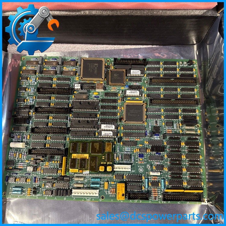
DS200TCCAG1BAA
Main Features and Engineering Considerations
Mark V analog processing
The primary engineering characteristic of the DS200TCCAG1BAA is that it combines analog I/O interface functions with local processing and programmable logic. The onboard 80196 processor and PROM devices distinguish it from passive Mark V termination boards such as the TBCA. The board participates in the processing and distribution of analog information within the Mark V control architecture.
JCC and JDD interfaces
JCC and JDD are two 50-pin interfaces that form an important part of the board’s internal signal architecture. The available records associate JCC and JDD with RTD input signals from the TBCA termination board. When replacing a TCCA, both connectors should be inspected for correct seating, pin damage, oxidation, and ribbon-cable condition.
4–20 mA signal handling
The TCCA architecture includes connections associated with CTBA 4–20 mA input and output signals. This does not mean that every physical pin on the board is a universal 4–20 mA channel. The actual signal allocation is determined by the Mark V terminal-board configuration and the turbine’s control drawings. Treating the board as a conventional 8-, 16-, or 32-channel PLC analog card is therefore misleading.
RTD signal path
The TCCA also receives RTD-related signals through JCC and JDD from the TBCA termination board. This is particularly important when troubleshooting turbine temperature channels. A bad reading can originate in the RTD sensor, field wiring, TBCA termination, ribbon cable, TCCA processing circuitry, or configuration/PROM data. Replacing the TCCA without checking the complete signal path can result in unnecessary board replacement.
Jumper configuration
The G1B TCCA family has three documented manually movable hardware jumpers. J1 controls the RS232 interface, JP2 selects an oscillator used for card-test settings, and JP3 is associated with factory testing. These settings should be compared against the original board and the applicable Mark V documentation before installation.
PROM and revision control
The PROM configuration deserves particular attention on legacy Mark V equipment. Field engineering discussions note that Mark V spare boards may not automatically include the same PROM configuration as the installed board, and that PROM revisions can be tied to the panel’s build and later technical updates. A replacement PCB should therefore be checked for the correct PROM population and revision before commissioning.
Legacy lifecycle
The Mark V platform is a mature legacy control system. The technical risk in sourcing a is not limited to whether the PCB powers up. A board can appear electrically healthy while having an incorrect firmware/PROM configuration, incompatible revision, damaged connector, or incorrect jumper arrangement. Bench testing under simulated Mark V conditions is preferable to visual inspection alone.
Application Scenarios
Gas Turbine Control
The TCCA board is used within Mark V gas-turbine control systems for analog signal processing and exchange between field termination circuitry and the control system.
Steam Turbine Control
Mark V steam-turbine installations can use the same TCCA architecture for analog process and turbine instrumentation, subject to the specific panel configuration.
Turbine Temperature Monitoring
RTD signals routed through TBCA termination hardware can be processed through the TCCA signal chain for bearing and other temperature measurements.
Pressure and Process Measurement
4–20 mA instrumentation connected through the applicable CTBA termination architecture can form part of the analog signal set handled by the TCCA system.
Legacy Mark V Maintenance
The board remains relevant as a replacement or repair component for operating Mark V installations where migration to a newer control platform has not yet occurred.
Engineer’s Guide: Field Pitfalls
1. Do not confuse TCCA with TBCA.
TCCA is the processing/interface board. TBCA is an RTD termination board. They perform different functions.
2. Do not use generic Ethernet specifications.
The available technical evidence supports internal Mark V interfaces and an RS232-related function, not a standalone Ethernet port.
3. Verify the PROM population.
A PCB with the correct DS200 number can still require the correct PROM configuration for the turbine panel.
4. Record jumper positions.
Before removing the original card, photograph and document J1, JP2, and JP3 positions.
5. Check JCC and JDD carefully.
Incorrect or partially seated ribbon cables can affect groups of analog/RTD signals simultaneously.
6. Check the terminal-board chain.
When an analog or RTD channel is abnormal, inspect the associated CTBA, TBCA, or TBQA termination hardware before assuming the TCCA has failed.
7. Match the complete suffix.
Do not purchase a generic “DS200TCCA” replacement without verifying the functional and artwork revisions.
8. Test before plant return.
A replacement should be checked for power-up behavior, processor/LED status, connector integrity, analog signal paths, applicable RS232 function, and turbine-specific I/O behavior.
Frequently Asked Questions
What is GE ?
It is a GE Mark V TCCA TC2000 Analog I/O Board containing an 80196 microprocessor, PROM devices, programmable logic, and multiple Mark V signal interfaces.
Is a passive terminal board?
No. Unlike a passive termination board, the TCCA contains a microprocessor and programmable logic and performs processing/interface functions within the Mark V architecture.
How many connectors does the board have?
The principal documented connectors are two 50-pin headers, JCC and JDD. The board also has other Mark V interface connectors associated with power, diagnostics, CTBA, TBCA, and TBQA signal paths.
Does it support 4–20 mA signals?
Yes, the documented TCCA architecture includes CTBA 4–20 mA input and output signal interfaces. The exact channel assignment depends on the Mark V panel wiring and application configuration.
Does it process RTD signals?
It participates in the RTD signal path through JCC and JDD connections to the TBCA termination board. The complete measurement function depends on the TCCA/TBCA/RTD system configuration.
Does have a processor?
Yes. The documented board uses an 80196 microprocessor.
Is a TMR voting controller?
That description is misleading. Some current listings call the TCCA a “TMR redundancy management” or “common control” board, but the stronger part-specific technical records identify as the TC2000 Analog I/O Board. Its role should be evaluated within the complete Mark V architecture rather than described as the dedicated TMR voting controller.
What should be verified before purchasing a replacement?
Verify the complete identifier, functional/artwork revision, PROM population, jumper positions, connector arrangement, associated CTBA/TBCA/TBQA boards, and the actual Mark V panel configuration.
Procurement Note
For a replacement order, specify GE — TCCA TC2000 Analog I/O Board in full. For used or refurbished hardware, request photographs of the complete nameplate, PCB revision markings, PROM devices, jumpers, connectors, and board condition.
The most important procurement issue is configuration matching rather than simply finding another TCCA board. Mark V field discussions specifically highlight the relationship between board revisions and PROM revisions, so a visually similar DS200TCCAG1B, DS200TCCAG1A, or other TCCA variant should not be treated as an automatic replacement without checking the site’s control documentation.
For engineering documentation, I would classify as a GE Mark V TCCA / TC2000 Analog I/O Board, not as a generic PLC analog module and not as a standalone TMR redundancy controller.