Description
GE DS200DTBCG1AAA Contact Output Termination Module
Product Introduction
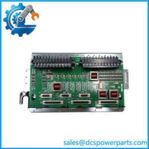
The GE DS200DTBCG1AAA is a Contact Output Termination Module used in the GE Mark V Speedtronic turbine control architecture. Its job is primarily at the field-interface level: it provides termination, relay-output routing, and connection between Mark V control electronics and external discrete loads. This makes the board a wiring and output-interface component rather than a standalone processor or conventional PLC analog I/O module. GE Mark V documentation and equipment records identify the DTBC as a relay/solenoid termination board associated with turbine control output circuits.
The GE DS200DTBCG1AAA provides two large terminal blocks, each reported with 110 signal-wire terminals, along with multiple plug connectors and ten hardware jumpers. The documented relay arrangement includes outputs 1–15 that can be configured for dry-contact service or 125 VDC solenoid applications, while outputs 16 and 17 are associated with fused solenoid circuits. Relay 18 incorporates a current-limiting resistor for a documented solenoid circuit, while outputs 19–30 are used as dry contacts. This arrangement reflects the board’s role in distributing and terminating discrete control outputs within a Mark V cabinet.
For replacement work, the GE DS200DTBCG1AAA should be matched by the complete part number, board revision, jumper configuration, terminal wiring, and associated Mark V terminal/control boards. A visually similar DS200 board is not automatically interchangeable. The exact field circuit matters, particularly where a relay output is being used to drive a solenoid or other energized load.
Technical Specifications
| Parameter | Specification |
|---|---|
| Product Model | DS200DTBCG1AAA |
| Manufacturer | General Electric (GE) |
| Product Series | Mark V / DS200 |
| Product Type | Contact Output Termination Module |
| Functional Acronym | DTBC |
| Primary Function | Contact/relay output termination |
| Relay Outputs | 30 relay positions documented |
| Terminal Blocks | 2 |
| Terminal Capacity | 110 signal-wire terminals per terminal block |
| Plug Connectors | 2 × 3-plug connectors; 1 × 2-plug connector |
| Hardware Jumpers | 10 |
| Output Configuration | Dry-contact and selected wetted/solenoid output circuits |
| Solenoid Circuit Voltage | 125 VDC for documented wetted-output configuration |
| Functional Revision | A |
| Artwork Revision | A |
| PCB Coating | Normal coating |
| Installation | GE Mark V control cabinet / termination assembly |
| Communication Protocol | None as a standalone communications function |
| Operating Accuracy | Not applicable; this is a relay/contact termination board |
| Protection Rating | Not independently established; verify cabinet-level environmental specification |
The 125 VDC figure applies to the documented wetted-output/solenoid configuration and should not be interpreted as a universal board supply rating.
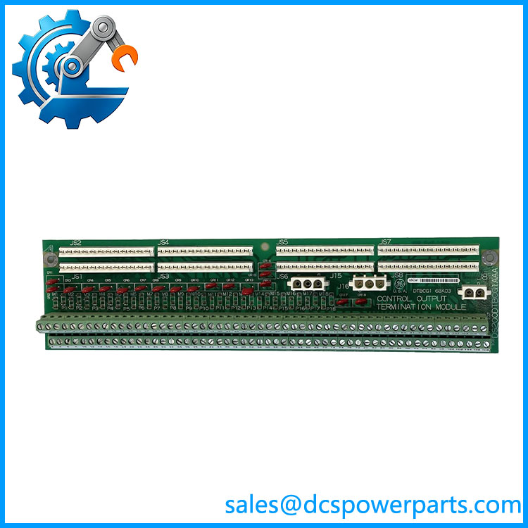
DS200DTBCG1AAA
Main Features and Engineering Considerations
Relay and Solenoid Interface
The main engineering value of the DS200DTBCG1AAA is its ability to organize Mark V relay outputs into practical field termination circuits. Documentation and field records identify 30 relay positions. Outputs 1–15 can be configured as dry contacts or as 125 VDC wetted outputs for solenoid service. Outputs 16 and 17 have dedicated fused-solenoid associations, while output 18 includes a current-limiting resistor for a documented solenoid circuit. Outputs 19–30 are documented as dry-contact outputs.
Jumper Configuration Matters
Ten hardware jumpers are associated with the board’s output configuration. This is not a board where replacing the PCB and simply reconnecting every wire should be treated as sufficient commissioning practice. Before removing an installed unit, record jumper positions and terminal assignments. A replacement board with different jumper settings can produce a different field-output behavior even when the PCB part number is identical.
Field Wiring Density
Two terminal blocks with 110 signal-wire terminals each make the DTBC a high-density termination assembly. This is useful in Mark V turbine cabinets but creates a practical replacement risk: documentation, wire tags, terminal numbers, and connector positions need to be preserved carefully. A wiring error on a relay-output board can affect valves, solenoids, permissives, or other turbine control functions.
System Compatibility
The belongs to the GE Mark V architecture. Several online listings incorrectly classify the part as an analog I/O card or Mark VIe component. The controlled identification is a Mark V Contact Output Termination Module / relay terminal board.
Do not treat the as a universal replacement for other DS200 terminal boards. Confirm the cabinet drawing, associated relay/control board, terminal-board revision, and actual field-output assignment before procurement.
Application Scenarios
- GE Mark V gas turbine control panels
- Steam turbine auxiliary control applications using Mark V architecture
- Turbine fuel, gas, cooling, and auxiliary solenoid control circuits
- Relay-driven field actuator interfaces
- Discrete output termination and distribution
- Mark V control cabinet refurbishment
- Legacy turbine control-system maintenance and spare-board programs
Engineer’s Guide: Field Pitfalls
1. Do not confuse it with an analog I/O board.
The DTBC is fundamentally a contact-output termination assembly. Online descriptions calling it an analog control card are inconsistent with the stronger DTBC functional identification.
2. Record every jumper before replacement.
The ten hardware jumpers are part of the output configuration. Photographing the original board before removal is inexpensive insurance.
3. Check whether the circuit is dry contact or wetted.
The documented output arrangement supports both dry-contact operation and selected 125 VDC solenoid circuits. Do not assume every relay position has the same electrical function.
4. Verify terminal numbering against the cabinet drawing.
With two high-density terminal blocks, wire identification alone may not be enough. Compare terminal numbers, connector positions, and Mark V core documentation.
5. Check the complete part number.
contains revision information. Do not replace it solely because another DTBC board has the same functional acronym.
6. Inspect associated boards.
The DTBC is an interface/termination component. Troubleshooting should include the upstream Mark V relay/control board and the downstream field wiring and loads.
Frequently Asked Questions
What is the GE ?
It is a GE Mark V Contact Output Termination Module, also described in some documentation as a connector relay terminal board or relay terminal board.
Is an analog input/output card?
No. The controlled functional identification is a Contact Output Termination Module. Some reseller pages incorrectly describe it as an analog I/O card, so that terminology should not be used for engineering classification.
How many relay outputs does it have?
Field documentation for the board identifies relay outputs 1–30. The output groups have different circuit arrangements, so the 30 positions should not be assumed electrically identical.
Does it support 125 VDC?
Selected output circuits can be configured for 125 VDC wetted/solenoid operation. This is an output-circuit specification, not a blanket statement that the entire board operates from a 125 VDC supply.
How many terminal connections are available?
Two terminal blocks are documented, with 110 signal-wire terminals per block.
Is it suitable for a Mark VIe system?
The reliable identification of this exact part number is GE Mark V. Listings that label as a Mark VIe component should not be used as the basis for a compatibility decision.
What should be checked before purchasing a replacement?
Confirm the complete part number, functional/artwork revision, jumper positions, terminal assignments, associated Mark V control/relay board, cabinet drawing, and the voltage/load requirements of the connected field circuits.
Procurement Note
For a replacement , prioritize exact part-number matching and documented functional equivalence over a generic “DTBC” description. For used or refurbished inventory, request clear photographs of the board identification, revision markings, terminal blocks, connectors, and jumper positions. For critical turbine service, functional testing of relay outputs and inspection of the terminal hardware should be part of incoming acceptance.