Description
GE DS200DTBBG1ABB Contact Input Expansion Termination Module
Product Introduction
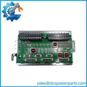
The GE DS200DTBBG1ABB is a Contact Input Expansion Termination Module used in the GE Mark V Speedtronic turbine control system. Its primary job is to terminate and route discrete contact signals into the Mark V control architecture. It is therefore a field-interface and termination component rather than a standalone processor or conventional PLC digital-input module. The documented application assigns this board to digital contact inputs 47 through 96, making it part of the larger contact-input acquisition path associated with the TCDA board.
The GE DS200DTBBG1ABB contains two terminal blocks with 95 signal-wire terminals each. The board also carries five hardware jumpers and multiple connector interfaces. Documentation identifies JRR as the interface carrying contact-input signals toward the TCDA board, while JY receives 125 VDC from the DTBA board. JRS/T is identified as an additional connector that is typically unused in the documented configuration. These relationships are important because the DTBB cannot be evaluated independently from the surrounding Mark V terminal and control boards.
For replacement work, the GE DS200DTBBG1ABB should be matched using the complete part number, board revision, terminal assignments, jumper positions, connector population, and cabinet location. The board is reported in Q11 and Q51 cores in the documented configuration. Because it carries a large number of field wires and ribbon cables, retaining the original board position and reproducing the approved cable routing is important for both signal integrity and cabinet cooling.
Technical Specifications
| Parameter | Specification |
|---|---|
| Product Model | DS200DTBBG1ABB |
| Manufacturer | General Electric (GE) |
| Product Series | Mark V / DS200 Speedtronic |
| Functional Acronym | DTBB |
| Product Type | Contact Input Expansion Termination Module |
| Alternate Product Description | Terminal Digital Connector Board |
| Primary Function | Digital contact-input termination and routing |
| Digital Input Assignment | Contact inputs 47–96 |
| Terminal Blocks | 2 |
| Terminals per Block | 95 |
| Total Terminal Positions | 190 |
| Hardware Jumpers | 5 |
| Primary Connector References | JRR, JY, JRS/T |
| Additional Connector Designations | JFF, JFG, JFH reported in board records |
| Associated Control Board | TCDA |
| Power Source Interface | JY, 125 VDC from DTBA in documented configuration |
| Input Voltage | 24–125 VDC reported for contact-input circuits |
| Board Dimensions | Approx. 3 × 11.5 in. |
| Mark V Group | Group 1 |
| Functional Revision | A |
| Secondary Revision | B |
| Artwork Revision | B |
| PCB Coating | Normal |
| Communication Protocol | None as a standalone network interface |
| Operating Accuracy | Not applicable as a signal-conditioning measurement module |
| Protection Rating | Not independently established |
| Operating Temperature | Not reliably established for the bare board |
The 24–125 VDC range should be treated as a documented contact-input application range, not as a universal standalone board power-supply specification.
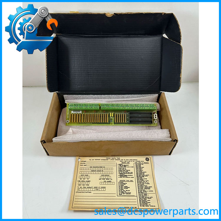
DS200DTBBG1ABB
Main Features and Engineering Considerations
Contact Input Expansion
The primary function of the DS200DTBBG1ABB is expansion and termination of discrete contact inputs. The documented input assignment covers contacts 47–96. This places the board in the Mark V contact-input acquisition chain rather than the analog signal path.
High-Density Field Termination
Two terminal blocks provide 95 signal-wire terminals each. That density is useful in a turbine cabinet but makes replacement work sensitive to terminal identification. Wire labels should be checked against the Mark V cabinet drawing rather than relying only on physical wire position.
TCDA Interface
The contact-input signals are routed toward the TCDA board through the documented interface. This means a fault appearing at the DTBB may originate from the field contact, wiring, terminal hardware, DTBB circuitry, interconnecting cable, or TCDA input circuitry. Replacing the board without checking the complete signal path can result in unnecessary board swaps.
DTBA Power Interface
The JY connector is documented as receiving 125 VDC from the DTBA board. This is particularly important during troubleshooting because the presence or absence of voltage at JY should be evaluated in the context of the Mark V cabinet’s power-distribution design. It should not be interpreted as a universal standalone 125 VDC supply specification for every circuit on the board.
Jumper Configuration
Five hardware jumpers are documented on the board. Their original positions should be photographed and recorded before removal. A replacement board should normally reproduce the installed configuration unless the engineering documentation specifies a controlled change.
Cable Routing
GE Mark V boards such as the DTBB can carry substantial quantities of field wiring and ribbon cables. Technical records specifically warn that routing power cables too close to signal wiring can introduce interference, while poorly arranged cable bundles can restrict cabinet airflow.
Application Scenarios
- GE Mark V gas turbine control systems
- GE Mark V steam turbine control systems
- GE Mark V wind turbine control applications
- Discrete contact-input termination
- Turbine auxiliary equipment status monitoring
- Relay/contact status acquisition
- Mark V Q11/Q51 core configurations
- Legacy turbine-control cabinet refurbishment
- Replacement of installed DTBB terminal boards
Engineer’s Guide: Field Pitfalls
1. Do not confuse DTBB with a generic digital input card.
The DTBB is a termination/interface board within the Mark V architecture. The actual signal-processing path includes associated control hardware such as TCDA.
2. Verify the input group.
The documented board handles contact inputs 47–96. Do not assume that another DTBB revision or similar terminal board uses the same contact numbering.
3. Record all five jumpers.
Photograph the installed jumper positions before removing the original board.
4. Check JRR, JY, and JRS/T.
JRR carries contact-input signals toward TCDA, JY receives 125 VDC from DTBA, and JRS/T is typically unused in the documented configuration. Confirm your cabinet drawing before reconnecting anything.
5. Do not assume 125 VDC is the only applicable field voltage.
The documented contact-input range includes 24 VDC through 125 VDC. The actual circuit voltage must be established from the installed cabinet and field devices.
6. Preserve cable routing.
Keep power and signal wiring separated where the cabinet design requires it. Improper routing can introduce electrical interference and restrict cooling airflow.
7. Match the complete revision.
The exact identifier carries functional and artwork revision information. A board that only matches the DTBB base designation should not automatically be treated as interchangeable.
Frequently Asked Questions
What is GE ?
It is a GE Mark V Contact Input Expansion Termination Module, also described as a Terminal Digital Connector Board.
What digital inputs does it terminate?
The documented configuration uses the board for digital contact inputs 47–96.
How many terminals does have?
It has two terminal blocks with 95 signal-wire terminals per block, for 190 terminal positions in total.
What is the input voltage?
Technical records report a 24 VDC to 125 VDC contact-input range. When configured for 24 VDC inputs, an external power supply is required. The actual field voltage should be confirmed from the cabinet documentation.
Which board receives the contact-input signals?
The documented JRR interface routes the contact-input signals to the TCDA board.
What is the purpose of the JY connector?
JY is documented as receiving 125 VDC from the DTBA board in the Mark V architecture.
Does have Ethernet or Modbus?
No standalone Ethernet, Modbus, or other network communication function has been established for this board. It is a Mark V termination/interface component.
Is this a Mark VIe board?
The exact is identified in the stronger technical records as a Mark V board. Some reseller pages incorrectly tag it as Mark VIe, but that should not be used as the basis for system compatibility.
Procurement Note
For a replacement , verify the complete part number, functional/artwork revisions, terminal assignments, five jumper positions, connector population, Q11/Q51 installation context, and the associated TCDA and DTBA hardware.
For refurbished inventory, request clear photographs of the board label, terminal blocks, connectors, jumpers, and PCB condition. Incoming checks should include terminal and connector inspection, jumper verification, continuity testing where appropriate, and functional testing against the intended Mark V contact-input configuration.