Description
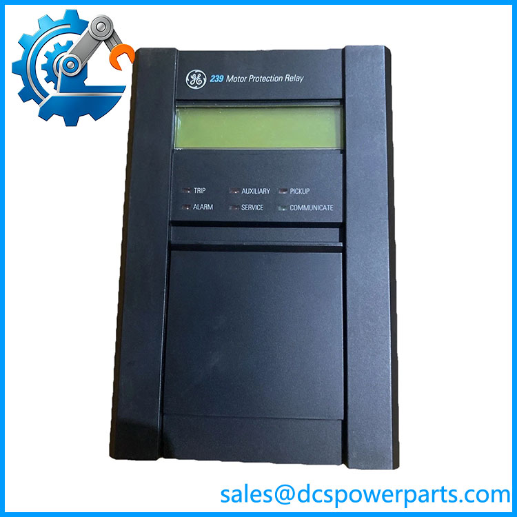
GE Multilin 239-AN Motor Protection Relay
Product Overview
The GE Multilin 239-AN is a member of GE’s Multilin 239 Motor Protection Relay family, designed to protect three-phase AC motors against electrical and process-related conditions that can cause motor damage. Its protection functions include phase overcurrent, ground fault, thermal modeling, phase unbalance, undercurrent, mechanical jam, locked-rotor/start protection, and other motor-protection functions. The relay uses true-RMS measurement with 16 samples per cycle for phase and ground current inputs. GE specifies 1 A and 5 A phase CT secondary inputs, while the ground-current section supports a 5 A CT or a 50:0.025 CT arrangement.
What distinguishes the GE Multilin 239-AN from a standard 239 configuration is the single isolated programmable analog output. The AN option provides selectable 0–1 mA, 0–20 mA, or 4–20 mA output ranges, with the output parameter programmable for values such as thermal capacity, percentage of full load, phase current, or RTD temperature. The relay also provides RS485 communications using Modbus RTU, allowing motor measurements and setpoints to be integrated into a plant monitoring or control system.
From a retrofit perspective, the 239-AN should be treated as a motor protection device first and an analog-output device second. It is not equivalent to a generic PLC analog-output card. The analog signal is derived from the relay’s internal motor-protection measurements and configuration, while the actual protection logic remains inside the 239. This distinction becomes important when replacing an obsolete relay or integrating the device with a PLC/DCS.
Product Introduction — Non-Templated
Motor protection becomes more complicated when the application requires both electrical protection and a usable analog representation of motor condition. The 239-AN addresses that combination by adding one isolated programmable analog output to the Multilin 239 protection platform. Depending on configuration, the output can represent phase current, thermal capacity, full-load percentage, or RTD temperature.
For a legacy motor protection replacement, the relay’s order code matters more than the basic “239” designation. GE documentation identifies 239-AN as one configuration and 239-RTD-AN as another, while modification numbers can add application-specific functions. The back-panel identification should therefore be checked before approving a replacement.
Key Technical Specifications
| Parameter | Specification |
|---|---|
| Product Model | 239-AN |
| Manufacturer | GE Multilin |
| Product Type | Motor protection relay with isolated analog output |
| Series | Multilin 239 |
| Motor Application | Three-phase AC motors |
| Phase CT Inputs | 1 A or 5 A secondary |
| Phase Current Measurement | True RMS, 16 samples/cycle |
| Phase Current Range | 0.1–11 × phase CT primary |
| Phase Current Frequency | 20–300 Hz |
| Phase Current Accuracy | ±2% of full scale |
| Ground CT Inputs | 5 A secondary or 50:0.025 |
| Ground Measurement | True RMS, 16 samples/cycle |
| Ground Current Frequency | 20–300 Hz |
| Analog Output | 0–1 mA / 0–20 mA / 4–20 mA |
| Analog Output Isolation | 36 VDC isolated, active source |
| Analog Output Accuracy | ±2% of full-scale reading |
| Maximum Analog Load | 2400 Ω at 0–1 mA; 600 Ω at 0–20 mA or 4–20 mA |
| Communications | RS485 |
| Protocol | Modbus RTU |
| Communication Rate | 1200–19.2 kbps |
| Standard Control Power | 70–265 VAC or 90–300 VDC |
| Low-Voltage Control Power | 20–48 VAC or 20–60 VDC with MOD 501 |
| RTD Configuration | Three RTDs, when specified |
| Operating Temperature | 0°C to 60°C |
| Storage Temperature | -40°C to 70°C |
| Output Relays | Form C NO/NC |
| Mounting | Panel-mounted protection relay |
| Configuration Software | 239PC |
The control-power range, CT specifications, communications, analog-output ratings, and environmental specifications are documented for the 239 platform. Exact installed options remain dependent on the complete order code and modification numbers.
Major Features / Practical Advantages
Complete Motor Protection Platform
The 239 was designed specifically around motor protection rather than general-purpose electrical measurement. Its functions include overload/thermal protection, phase overcurrent, ground fault, unbalance, undercurrent, mechanical jam, and start-related protection. This allows the relay to respond to both electrical faults and certain process conditions affecting the motor.
The undercurrent function, for example, can be useful on pumps where loss of suction or a closed discharge condition needs to be detected. Mechanical-jam protection addresses a different failure mechanism, using motor current behavior to identify abnormal loading. These functions should be evaluated against the actual motor starting characteristics rather than enabled blindly.
Multilin 239-AN
True-RMS Current Measurement
The phase and ground current measurement circuits use true-RMS conversion with 16 samples per cycle. GE specifies 1 A and 5 A phase CT secondary inputs, with a phase-current measurement range of 0.1 to 11 times the phase CT primary and an accuracy of ±2% of full scale.
That architecture makes correct CT selection particularly important. A relay replacement should retain the installed CT secondary rating and verify the programmed full-load-current value. Installing a physically compatible relay with incorrect CT settings can produce a protection problem even though the relay itself appears to operate normally.
Isolated Programmable Analog Output
The AN option adds one isolated analog output. The available ranges are 0–1 mA, 0–20 mA, and 4–20 mA, with a maximum load of 2400 Ω for the 0–1 mA range and 600 Ω for the 0–20 mA and 4–20 mA ranges. GE specifies 36 VDC isolation and ±2% full-scale accuracy.
The output parameter is programmable. Depending on configuration, it can represent thermal capacity, percentage of full load, phase current, or one of the RTD temperatures. This makes the relay useful when the PLC or DCS needs a continuous process variable without polling every value through serial communications.
RS485 and Modbus RTU
The 239 provides RS485 serial communications and uses Modbus RTU. The documented communication range is 1200 to 19.2 kbps. Through the communications interface, the system can read actual values, access setpoints, and execute supported commands.
For a modern DCS integration, this is a legacy serial architecture. If the plant network is Ethernet-only, an appropriate serial gateway may be required. Do not assume that the presence of an RS485 port means native Ethernet capability.
Thermal Motor Model
Thermal modeling is a central function of the 239. The relay maintains separate start and run protection behavior and uses programmable cooling characteristics. GE documents a programmable stopped-motor cooling time from 1 to 5000 minutes and separate thermal treatment for starting and running conditions.
This matters on high-inertia motors and applications with frequent starts. The relay is not merely looking for instantaneous overcurrent; its thermal model tracks motor heating and can impose restart lockout when the calculated thermal state requires it.
RTD Temperature Monitoring
Where the RTD option is installed, the 239 can monitor three RTDs, with configurations supporting stator and/or bearing temperature measurement. GE documentation lists programmable RTD types including platinum, nickel, and copper sensor types.
The exact RTD arrangement should therefore be confirmed from the installed order code rather than inferred solely from 239-AN. A 239-AN without the RTD option is not equivalent to a 239-RTD-AN.
Legacy Replacement Considerations
The Multilin 239 is a mature/legacy protection platform. That is not automatically a reason to reject it. In an operating plant, matching the existing motor-protection philosophy, CT ratios, wiring, trip/alarm logic, analog signal scaling, and Modbus register mapping can be more important than installing a newer relay that requires a complete redesign.
For a replacement, however, retain the original settings before removing the existing unit. GE specifically recommends providing the main program version, modification number, and product order code when an exact replacement is required.
Related Products
- GE Multilin 239 — Base 239 motor protection relay family. The exact option structure determines whether RTD monitoring, analog output, harsh-environment coating, and other modifications are present.
- GE Multilin 239-RTD — 239 configuration with three RTD inputs. Use when stator/bearing temperature monitoring is required without assuming the isolated analog-output option.
- GE Multilin 239-RTD-AN — Combines the three-RTD configuration with the isolated programmable analog output. This can be the closer match when an existing installation uses both temperature monitoring and a 4–20 mA signal.
- GE Multilin 239-H — 239 configuration incorporating harsh-environment conformal coating. It should not be substituted for a standard relay without reviewing the cabinet/environment requirements.
- GE Multilin 239 with MOD 501 — Low-voltage control-power version supporting 20–60 VDC / 20–48 VAC instead of the standard control-power range.
- GE Multilin 239 with MOD 512 — Configuration supporting a 1 A ground CT input.
- GE Multilin 239 with MOD 513 — Configuration for Class I Division 2 applications where the applicable certification and installation requirements are met.
- GE Multilin 239 with MOD 506 — Configuration providing a custom programmable overload curve.
These are configuration relationships within the 239 family, not blanket interchangeability statements. The complete nameplate/order code should determine the correct replacement.
Frequently Asked Questions
Is the 239-AN an analog-output module?
No. The AN suffix identifies the single isolated programmable analog-output option on a GE Multilin 239 motor protection relay. The primary device remains a motor protection relay.
What does the analog output represent?
The output is programmable. GE documents thermal capacity, percentage of full load, phase current, and RTD1/RTD2/RTD3 temperature as possible output parameters, depending on the installed configuration.
Can I use the 239-AN with a 5 A CT?
Yes. The standard 239 phase-current inputs support both 1 A and 5 A CT secondaries. The ground-current section has its own CT requirements and should be checked separately.
Can I hot-swap this relay?
Do not treat the 239-AN as an unrestricted hot-swap device. It is wired into motor CT circuits, control power, trip/alarm contacts, RTDs where fitted, and potentially the starter control circuit. Replacement should be performed under the site’s approved electrical isolation and motor-protection maintenance procedure.
Does the 239-AN support firmware v3.1?
Do not infer that from 239-AN. Published GE manuals identify specific 239 firmware revisions, including 2.6x and 2.7x documentation. The installed firmware must be checked from the actual relay. GE also recommends recording the main program version and modification number when an exact replacement is required.
Can I connect the 239-AN directly to a modern Ethernet PLC?
Not natively through Ethernet. The documented communications interface is RS485 with Modbus RTU, at up to 19.2 kbps. An appropriate serial-to-Ethernet gateway may be used where the plant architecture requires Ethernet connectivity.
Is 239-AN the same as 239-RTD-AN?
No. The 239-RTD-AN configuration adds the three-RTD option to the analog-output configuration. The basic 239-AN designation alone should not be assumed to include those RTD inputs. GE’s identification documentation explicitly distinguishes 239-AN from 239-RTD-AN.
Can a New Surplus 239-AN be used as a direct replacement?
Potentially, but verify the complete order code, modification numbers, firmware, control-power range, CT ratings, RTD configuration, analog-output scaling, and existing protection setpoints first. A 239 with the correct base model but a different modification set is not necessarily functionally equivalent.
Procurement Note
For a GE Multilin 239-AN, procurement should focus on the complete configuration rather than the 239-AN string alone.
Before accepting a replacement, verify:
- Complete product order code from the rear nameplate.
- Main program/firmware version.
- Modification numbers.
- Control-power range.
- Phase CT secondary rating — 1 A or 5 A.
- Ground CT arrangement.
- RTD option and sensor type, if installed.
- Analog-output range and programmed parameter.
- /Modbus communication settings.
- Existing motor-protection setpoints.
- Trip, alarm, auxiliary, and service relay wiring.
- Environmental/certification requirements of the installation.
The analog output is particularly easy to overlook. A replacement may physically fit and communicate correctly while still producing the wrong 4–20 mA variable or scaling if the original configuration is not recovered.
GE’s own documentation states that an exact replacement should be ordered using the main program version, modification number, and product order code found on the relay label. That is the right procurement standard for a legacy 239 installation.