Description
Key Technical Specifications
| Parameter | Specification |
|---|---|
| Product Model | 7DO138.70 |
| Manufacturer | B&R Industrial Automation |
| Product Family | System 2003 |
| Product Type | Digital Output Module |
| Number of Outputs | 8 |
| Output Technology | FET / semiconductor |
| Rated Output Voltage | 24 VDC |
| Permitted Output Voltage | 11.4–30 VDC |
| Output Current | 0.5 A per channel |
| Maximum Total Current | 4 A |
| Output Configuration | Push/pull |
| Output Voltage Drop | ≤0.6 V at 0.5 A |
| Maximum Switching Frequency | 1 kHz |
| Maximum Capacitive Load | 20 nF |
| Short-Circuit Protection | Yes |
| Overload Protection | Yes |
| Reverse Polarity Protection | Yes |
| Short-Circuit Current | Approximately 0.55–1.5 A |
| Power Consumption | Max. 0.4 W |
| Module Interface | CP interface |
| Adapter | AF101 |
| Terminal Block | TB712, ordered separately |
| Mounting | B&R 2003 screw-in module |
| Protection Rating | IP20 |
| Operating Temperature | 0–60°C horizontal; 0–50°C vertical |
| Storage Temperature | -25–70°C |
| Humidity | 5–95%, non-condensing |
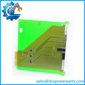
B&R identifies the 7DO138.70 as an eight-channel digital output module with 24 VDC FET outputs rated at 0.5 A per channel. The maximum total output current is specified as 4 A.
The module has short-circuit, overload, and reverse-polarity protection. Its documented maximum switching frequency is 1 kHz, which is an important distinction from faster System 2003 output modules such as the 7DO135.70.
Application Scenarios & Pain Points
A 24 VDC output is not automatically suitable for every actuator in a cabinet. The load’s current, inrush behavior, switching frequency, and inductive characteristics all affect whether the semiconductor output is appropriate.
- Solenoid and valve control: Eight 24 VDC FET channels can operate suitable low-voltage DC solenoids and valves, provided each load remains within the 0.5 A channel rating.
- Contactor and relay control: The outputs can drive appropriately rated DC coils, though coil suppression and inrush current should be checked before commissioning.
- Machine automation: Used for discrete actuator commands such as clamps, brakes, cylinders, interlocks, and other 24 VDC machine devices.
- Legacy System 2003 cabinets: The screw-in format makes it particularly relevant where an older B&R controller is being maintained rather than replaced wholesale.
Field note: A nominal 24 VDC coil drawing 0.4 A may look acceptable on paper. If it has a substantial inrush current or is repeatedly switched at high frequency, the application deserves closer review. The 7DO138.70 is rated at 0.5 A per channel, but that number should not be treated as a universal recommendation for every inductive load.
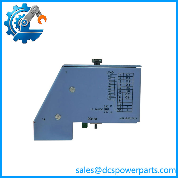
7DO138.70
Related Products
- B&R 7DO135.70 — Four-channel FET output module for 12–24 VDC loads at 0.1 A per output. It supports much faster switching, up to 100 kHz, but has significantly lower current capacity than the 7DO138.70.
- B&R 7DI140.70 — Ten-channel 24 VDC digital input module from the same System 2003 family. It complements the 7DO138.70 for sensor-input and actuator-output sections.
- B&R 7DI138.70 — Ten-channel 24 VDC digital input module. It is the input-side counterpart for conventional discrete machine signals, rather than an output replacement.
- B&R 7DO164.70 — A different System 2003 digital-output option. Its output electrical characteristics differ from the 7DO138.70, so compare the actual load and switching requirements before considering it as an alternative.
- B&R 7DO720.7 — Relay-output module for applications where mechanical relay contacts are required. It is not a direct semiconductor-output substitute; the load voltage, current, switching frequency, and isolation requirements need review.
- B&R 7DO721.7 — Another relay-output module in the System 2003 family. It is more appropriate for applications requiring relay contacts rather than FET switching.
- B&R 7AI261.7 — Specialized one-channel 24-bit strain-gauge input module. It shares the broader System 2003 ecosystem but handles measurement signals rather than digital actuator commands.
- B&R 7TB712.9 — Twelve-pin screw-clamp terminal block associated with the 2003 screw-in modules. It is a field-connection accessory and should be checked separately when sourcing a replacement.
- B&R 7TB712.91 — Cage-clamp version of the terminal block. Select it when the installed cabinet uses the corresponding spring/cage-clamp termination arrangement.
The Engineer’s Guide: Field Pitfalls to Avoid
⚠️ Do not confuse 7DO138.70 with 7DO135.70.
Both are FET output modules, but their electrical characteristics are quite different. The DO138 provides 0.5 A per channel and 1 kHz maximum switching, while the DO135 provides 0.1 A per channel with much higher switching capability.
⚠️ Check inductive-load suppression.
Solenoids, contactor coils, and brakes can generate significant voltage transients when switched off. Confirm the load has the required suppression and that the output protection is not being repeatedly stressed.
⚠️ Watch the total current.
Even if each individual channel remains below 0.5 A, the module has a documented 4 A maximum total output current. Check the combined load when several outputs operate simultaneously.
Practical check: Before replacing the module, document every output’s load type, measured operating current, fuse rating, PLC assignment, and field polarity. After installation, test each channel under its real load rather than using only a multimeter with no load connected.
Frequently Asked Questions (FAQ)
What is B&R 7DO138.70 used for?
The 7DO138.70 is an eight-channel System 2003 digital output module designed to switch suitable 24 VDC loads through semiconductor FET outputs. Typical uses include valves, solenoids, contactors, brakes, and other discrete machine actuators.
How much current can each 7DO138.70 output handle?
Each output is rated for 0.5 A, while the maximum total output current for the module is 4 A. The permitted output voltage is approximately 11.4–30 VDC.
Is 7DO138.70 a relay output module?
No. It uses FET semiconductor outputs, not mechanical relay contacts. That means there is no mechanical contact wear, but inductive loads still need appropriate suppression and the semiconductor’s voltage/current limitations must be respected.
Can I replace 7DO135.70 with 7DO138.70?
Not automatically. The DO138 has more output current capacity, but the two modules have different electrical specifications and switching-frequency capabilities. If the original application relies on the DO135’s high-speed switching, a DO138 may not provide equivalent behavior.
Does 7DO138.70 include the terminal block?
The B&R product documentation identifies the TB712 terminal block as a separate accessory. Confirm whether your replacement quotation covers only the electronic module or also the field termination hardware.
Can 7DO138.70 be used for high-frequency pulse output?
It is not the preferred System 2003 option for very high-frequency pulse generation. The documented maximum switching frequency is 1 kHz. For applications requiring substantially faster switching, the electrical requirements should be compared with a module such as the 7DO135.70, which is specified for much higher switching frequencies.