Description
Key Technical Specifications
| Parameter | Specification |
|---|---|
| Product model | PPC-R02.2N-N-Q1-NN-NN-FW |
| Manufacturer | Bosch Rexroth Indramat |
| Product family | PPC-R02.2 |
| Hardware series | Series 2 |
| Housing design | RECO unit |
| Product type | Programmable control unit |
| Communication option | DAQ03 Link Ring cross communication |
| DAQ03 slot | U2 |
| Other expansion slots | U3 and U4: covers / no option cards |
| Nominal supply voltage | 24 VDC |
| Permissible supply range | 19.2–30 VDC |
| Digital inputs | 3 |
| Digital outputs | 2 |
| Digital output current | 0.5 A |
| Maximum power | 52 W |
| Maximum current consumption | 1.2 A |
| I/O bus supply, 5 V | 3.0 A |
| I/O bus supply, 24 V | 2.3 A |
| Protection rating | IP20 |
| Operating temperature | 0–45 °C |
| Dimensions (W × H × D) | 83.7 × 192 × 150 mm |
| Weight | Approx. 1.3 kg |
| Firmware designation | FW; firmware ordering/configuration must be checked against the installed unit |
Electrical and dimensional values are published for this configuration’s PPC-R02.2 control-unit family. Confirm the nameplate and hardware revision before using them as acceptance criteria for a replacement.
Product Introduction
The Bosch Rexroth Indramat PPC-R02.2N-N-Q1-NN-NN-FW is a Series 2 RECO-format programmable control unit used in industrial motion-control systems. Its configuration includes a DAQ03 option card for Link Ring cross communication in slot U2. This makes the Q1 configuration distinct from a base PPC-R02.2 unit without the communication option. The PPC platform can serve PLC and numerical-control functions within coordinated machine-control applications.
For replacement work, matching the PPC-R02.2 family alone is not sufficient. The DAQ03 option, slot assignment, firmware build, and application configuration all affect system behavior. The ordering suffix FW also matters: verify the firmware supplied with the unit against the machine’s original configuration before commissioning.
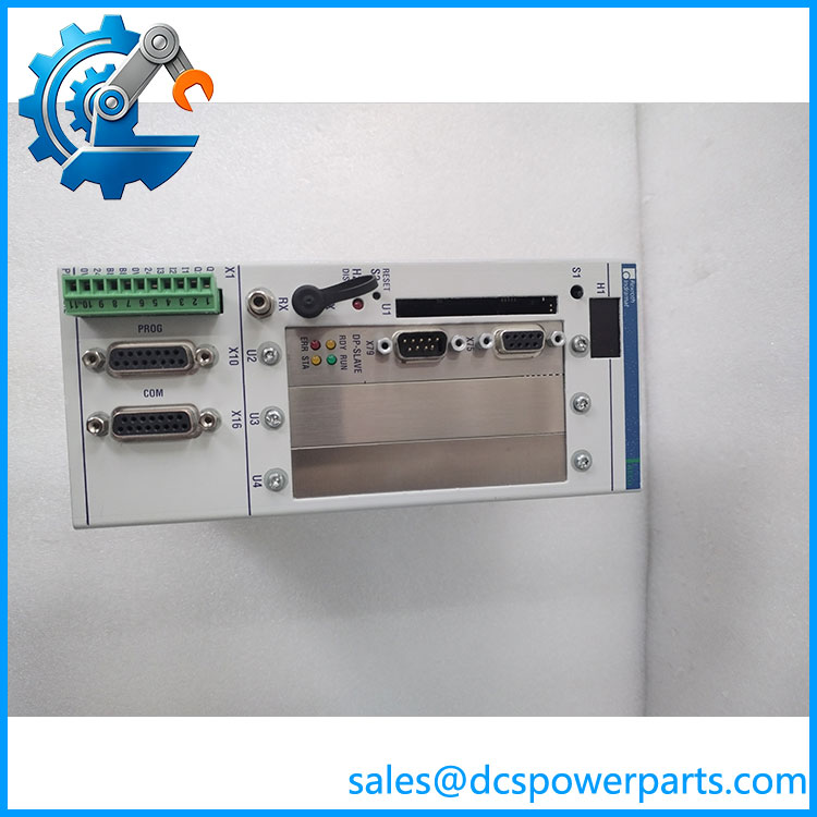
PPC-R02.2N-N-Q1-NN-NN-FW
Application Scenarios & Field Pitfalls
In a machine with several coordinated motion axes, the controller must exchange the right data with other control nodes while maintaining the expected machine sequence. The DAQ03 Link Ring option supports the cross-communication arrangement documented for this hardware configuration. It should not be treated as a generic Ethernet or fieldbus interface; the machine’s original network topology and controller project determine how it is used.
Typical application areas
- Multi-axis machine tools: Coordination of motion-control tasks and machine sequences where the PPC platform is used as a numerical-control or PLC controller.
- Packaging and converting equipment: Communication between control nodes in machines with synchronized motion and sequence operations.
- Printing machinery: Cross-communication between motion-control sections where timing and data exchange are part of the machine architecture.
- Special-purpose production equipment: Centralized or distributed control arrangements built around the .2 platform.
Field pitfalls to check
1. DAQ03 is not interchangeable with other option cards. The Q1 code identifies the Link Ring cross-communication configuration. A base .2 or a unit with a different option-card code may not provide the same network function. Confirm the slot population against the project manual and installed hardware.
2. Firmware compatibility is a commissioning issue. The FW suffix does not, by itself, establish that the firmware version matches the running machine. Check the firmware typecode, project version, and any application-specific dependencies before installing a replacement.
3. Do not overlook the existing network setup. Record Link Ring connections, node configuration, and controller communication settings before removing the original unit. After installation, verify communication status and machine interlocks before enabling motion.
4. Check the power and cabinet conditions. The published supply range is 19.2–30 VDC and the enclosure rating is IP20. Verify the 24 VDC supply under load, protective grounding, cabinet environment, and mounting arrangement. IP20 does not provide protection against water or conductive dust.
Related Products
These are related .2 configurations, not automatic substitutes. Their option-card populations differ:
- .2N-N-NN-NN-NN-FW — Base configuration without expansion cards; does not include the Q1/ Link Ring option.
- .2N-N-N1-NN-NN-FW — Uses an NSW01 option for a 16-output PLS interface rather than the communication option.
- .2N-N-N1-N2-NN-FW — Uses two NSW01 cards for a 32-output PLS interface.
- .2N-N-Q1-P2-NN-FW — Combines the Link Ring option with a DPS01 PROFIBUS slave interface.
These configuration distinctions are documented in the .2 hardware and firmware configuration table.
Procurement and replacement note: Specify the complete typecode, including every suffix, rather than ordering by .2 alone. Before accepting a replacement, compare the nameplate, card, firmware identification, connector arrangement, and application requirements with the removed controller. A matching family designation does not establish drop-in compatibility.