Description
Basler DECS-200-2L | Digital Excitation Control System | Generator AVR & Excitation Control
Key Technical Specifications
| Parameter | Specification |
|---|---|
| Manufacturer | Basler Electric |
| Model | DECS-200-2L |
| Product Family | DECS-200 |
| Product Type | Digital Excitation Control System |
| Primary Application | Synchronous-generator excitation |
| Main Control Modes | AVR, FCR, VAR, Power Factor |
| Excitation Output Classes | 32 / 63 / 125 VDC |
| Maximum Excitation Current | 15 A DC |
| Control Power | 24/48 VDC class |
| Style L Control-Power Range | 16–60 VDC |
| Excitation Power Input | 60 / 120 / 240 VAC nominal, depending on output class |
| Communication Ports | Front RS-232, side RS-232, RS-485 |
| Remote Protocol | Modbus on RS-485 |
| Configuration Software | BESTCOMS |
| Display | Front-panel LCD |
| Event Recording | Sequence of Events recording |
| Oscillography | Integrated disturbance recording |
Basler’s manual specifies three communication ports: a front RS-232 port for PC/BESTCOMS communication, a side RS-232 port for redundant DECS-200 communication, and an RS-485 port for remote communication. The RS-485 interface supports Modbus over distances up to approximately 1,200 m under the documented installation conditions.
Important Rating Note
The DECS-200 is configurable around different excitation output classes. Basler documentation identifies 32 VDC, 63 VDC, and 125 VDC output configurations, with the system capable of up to 15 A DC. Do not use generic reseller figures such as 0–10 A or 0–240 VDC to size a replacement; the actual DECS-200 configuration and excitation system determine the applicable rating.
Product Introduction
The Basler DECS-200-2L is a microprocessor-based digital excitation control system for synchronous generators. It regulates generator terminal voltage and can operate in field-current, VAR, or power-factor control modes while providing excitation limiting and generator protection functions.
The 2L designation is significant during replacement. The 2 option provides external/internal autotracking, while the L option identifies the applicable control-power arrangement. A with a different style or option code should not automatically be considered a drop-in replacement.
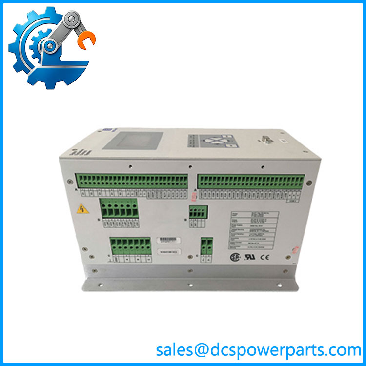
DECS-200-2L
Application Scenarios & Field Pitfalls — Engineer’s Perspective
Engineering Pain Point
The sits directly in the generator excitation loop, so replacement is more than a matter of matching enclosure dimensions. Excitation-source voltage, field current, sensing transformers, control-power supply, operating modes, limiters, and generator protection settings all need to correspond with the original application.
Typical Applications
- Synchronous generator AVR systems for automatic terminal-voltage regulation.
- Industrial power-generation equipment requiring field-current and voltage regulation.
- Utility-connected generators requiring VAR or power-factor control.
- Redundant excitation systems using coordinated units and autotracking.
Basler documents AVR, FCR, VAR, power-factor control, soft-start voltage buildup, excitation limiting, generator protection, sequence-of-events recording, and oscillography as part of the feature set.
Technical Pitfalls to Avoid
- Do not confuse the option code with the excitation-output rating.
2Ldescribes configuration options; it does not by itself mean 32 VDC, 63 VDC, or 125 VDC field output. Confirm the actual configuration and generator field requirements. - Verify the control-power source.
The has different control-power styles. Basler’s manual specifically distinguishes the 16–60 VDC XL arrangement from the higher-voltage XC arrangement. Applying the wrong control supply can damage the controller. - Check excitation-source voltage before energizing.
The PWM excitation power stage receives operating power from the generator output through a transformer or, alternatively, from a PMG. The required AC input depends on the selected DC excitation-output class. - Preserve the original BESTCOMS settings.
AVR gains, sensing configuration, limiters, protection thresholds, startup behavior, and field-current settings are application-specific. A replacement unit should be loaded with the correct configuration rather than commissioned from default parameters. - Do not assume newer communications specifications.
The OEM manual documents RS-232 and RS-485/Modbus. Claims that this older -2L inherently provides IEC 61850, Modbus TCP, or redundant Ethernet should not be applied to the unit without a specific hardware/configuration reference.
Related Products
- — Base digital excitation-control platform supporting generator voltage, field-current, VAR and power-factor regulation.
- — configuration with different tracking options; verify the complete style before substitution.
- — Related tracking configuration providing external/internal autotracking.
- Basler DECS-200-2L — The specific 24/48 VDC control-power and autotracking configuration addressed here.
- — Different control-power/style configuration; not automatically interchangeable with the L version.
- — Another style designation within the family; complete ordering information must be checked.
- Basler ICRM-15 — Inrush Current Reduction Module used with applicable installations.
- Basler IDP-800 — Interactive display option associated with applications.
- Basler DECS Freewheeling Diode Module — Used in certain dual- excitation arrangements.
Procurement Check
For a DECS-200-2L replacement, verify:
- Exact model:
- Complete Basler nameplate/style information
- Control-power input and polarity
- Excitation output class: 32, 63, or 125 VDC
- Maximum required field current
- Generator field resistance and field forcing requirements
- Generator PT/CT sensing configuration
- AVR/FCR/VAR/PF operating modes
- Excitation limiter settings
- Autotracking arrangement
- Redundant-DECS wiring, if applicable
- RS-485/Modbus wiring
- BESTCOMS configuration file
- Firmware revision
- Existing ICRM/freewheeling-diode arrangement
- Generator commissioning records
Recommended procurement description:
Basleic Digital Excitation Control System, Series, External/Internal Autotracking, 24/48 VDC Control-Power Configuration, Generator AVR/Excitation Control — verify excitation output class and complete configuration before replacement.
The critical point is that is a complete generator excitation controller, not simply a voltage regulator board. Its power stage, sensing circuits, control logic, limiters, protection functions, and configuration all form part of the excitation system.