Description
Key Technical Specifications
| Parameter | Specification |
|---|---|
| Model | FV223-M2 |
| Manufacturer | GEC / ALSTOM |
| Product Family | GECOSTAT Excitation System |
| Product Type | Diode Failure Detector |
| Primary Application | Brushless generator excitation monitoring |
| Monitoring Target | Rotating rectifier bridge diodes |
| Fault Detection | Open-circuit and short-circuit diode failures |
| Monitoring Channels | Positive and negative diode groups |
| Control Supply | 24 VDC |
| Operating Voltage Range | 18–30 VDC (reported; verify against original manual) |
| Status Indicators | Power, DIC Diode Fault, SIC Diode Fault |
| Diagnostic Function | Built-in local test circuit |
| Alarm Output | Fault relay contacts |
| Installation | Excitation control cabinet / GECOSTAT rack |
| Operating Temperature | Exact OEM rating requires confirmation |
| Product Lifecycle | Discontinued / legacy equipment |
Specification caution: Public technical references consistently identify the FV223-M2 as a GECOSTAT exciter diode failure detector. However, detailed electrical ratings and terminal assignments are not consistently documented. Confirm the original equipment drawings before using unverified current, contact-rating, or dimensional values.
Product Introduction
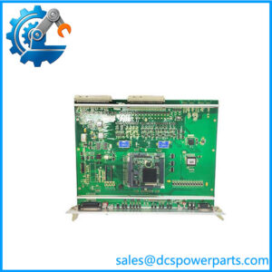
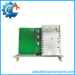
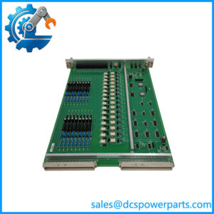
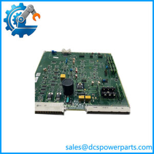
ALSTOM FV223-M2 GECOSTAT Excitation Diode Failure Detector
The ALSTOM FV223-M2 is a diode failure detection module used in GECOSTAT generator excitation systems. It monitors the rotating rectifier bridge of brushless synchronous generators, identifying abnormal diode conditions such as open-circuit and short-circuit failures. Its diagnostic signals help operators identify rectifier problems before they develop into more serious excitation-system faults.
The module provides local fault indication and alarm signaling to the excitation control system. For power plant maintenance teams, retaining a compatible FV223-M2 can help preserve existing generator protection and monitoring arrangements without immediately replacing the complete excitation control system.
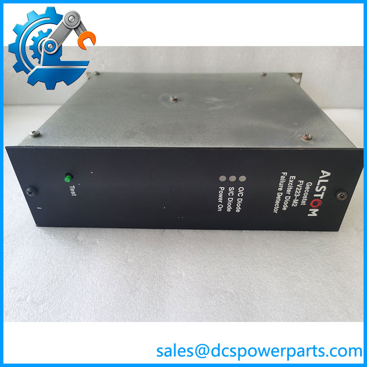
FV223-M2
Application Scenarios & Field Pitfalls (The Engineer’s Perspective)
Engineering Pain Point
A brushless synchronous generator can continue operating while developing a diode fault in its rotating rectifier bridge. The problem may initially appear as abnormal excitation behavior, increased ripple, or unstable generator operating conditions.
Without dedicated diode monitoring, identifying the defective rectifier component can require additional testing and generator shutdown procedures.
The FV223-M2 addresses this diagnostic requirement by monitoring excitation rectifier diode conditions and providing fault indications. It is a monitoring and protection-related component, not the main automatic voltage regulator. That distinction matters when troubleshooting generator excitation problems.
Typical Applications
- Thermal Power Plants: Monitoring rotating rectifier diode conditions in steam turbine generator excitation systems.
- Hydroelectric Power Stations: Detecting rectifier diode failures in brushless synchronous generator excitation assemblies.
- Gas Turbine Power Plants: Monitoring excitation diode faults to support generator protection and maintenance.
- Industrial Power Generation: Maintaining excitation monitoring functions in large synchronous generators.
- Heavy Industrial Drives: Supporting excitation rectifier diagnostics in compatible brushless synchronous motor installations.
Technical Pitfalls to Avoid
1. Do Not Confuse Diode Detection with AVR Regulation
The is a diode failure detector. It does not replace the automatic voltage regulator or the main excitation control module.
When investigating an excitation fault, distinguish between:
- Generator voltage regulation problems.
- Rotating rectifier diode failures.
- Excitation supply abnormalities.
- Field winding faults.
- Monitoring circuit or alarm relay failures.
Replacing the diode detector will not correct an underlying AVR or rectifier hardware problem.
2. Verify DIC and SIC Monitoring Connections
The module monitors diode conditions associated with the rectifier bridge’s positive and negative groups.
Incorrect sensing connections can produce misleading fault indications or prevent the module from detecting an actual diode failure.
Before replacement:
- Record the original sensing connections.
- Check cable identification against the excitation-system drawings.
- Verify signal polarity and terminal assignments.
- Compare the replacement module’s revision with the installed unit.
Do not reconnect sensing wires based only on physical connector similarity.
3. Perform a Controlled Functional Test
The includes a local testing function according to available product descriptions.
A useful maintenance inspection should include:
- Verification of the control supply.
- Inspection of power and fault indication LEDs.
- Controlled operation of the built-in test function.
- Verification of fault relay contact changes.
- Confirmation that the excitation control system receives the expected alarm.
Never simulate a diode failure by disturbing live rotating excitation connections. Follow the generator manufacturer’s isolation and commissioning procedures.
Procurement and Quality Inspection
The is a legacy, discontinued component. Replacement procurement requires careful revision and functional verification.
Ask the supplier for:
- Actual front and rear photographs.
- Complete identification.
- PCB revision information.
- Connector and terminal condition.
- 24 VDC power-up test results.
- Diode fault indication test results.
- Alarm relay functional test records.
For previously operated units, cosmetic condition is not sufficient. A module that powers up may still have defective sensing or relay circuits.
Related Products
The following models are associated with GECOSTAT and related generator excitation control functions. Confirm system-specific compatibility before substitution.
| Model | Product Description | Relationship and Application |
|---|---|---|
| FV200-M2 | Excitation fault detector module | Related excitation protection module providing under-voltage and over-voltage fault detection. Complements the diode monitoring function. |
| MC15-M2 | Excitation manual control module | Provides manual excitation control and adjustment functions. Used when manual control of generator excitation is required. |
| FF100-M2 | VT fuse failure detector | Monitors voltage-transformer fuse failure conditions in the excitation sensing circuit. Helps distinguish voltage-sensing problems from generator excitation faults. |
| GECOSTAT AVR | Automatic voltage regulator system | Main generator voltage regulation system. The supplies supplementary diode fault monitoring rather than performing AVR regulation. |
| Generator Rotating Rectifier Assembly | Rotating diode bridge | The actual monitored assembly. Contains the rectifier diodes whose failure conditions are detected by the . |
| Generator Excitation Transformer | Excitation power transformer | Supplies excitation-related power in compatible arrangements. Its electrical configuration must match the generator excitation design. |
| Excitation Control Relay Assembly | Protection and alarm interface | Receives fault signals and supports alarm or interlocking functions in the excitation control cabinet. |
| Generator AVR Control Module | Automatic excitation control module | Regulates generator terminal voltage and excitation current. It performs a different function from the . |
Final Engineering Recommendation
The ALSTOM is a specialized GECOSTAT excitation-system diode failure detector. Its importance lies in identifying rotating rectifier faults before they develop into more serious generator operating problems.
For replacement procurement, prioritize three checks:
- Exact hardware and PCB revision.
- Compatibility with the existing GECOSTAT excitation cabinet.
- Verified diode fault detection and alarm relay operation.
Do not treat the as a generic DCS input card or AVR replacement. Its sensing connections and protection role are specific to generator excitation equipment.