Description
ABB SPCJ4D34-AA Motor Protection Relay Module
Product Overview
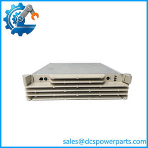
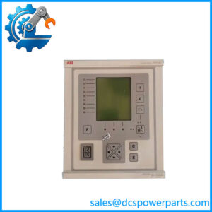
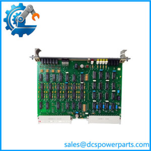
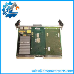
The ABB SPCJ4D34-AA is the motor protection relay module used within ABB’s SPAM 150 C protection architecture. It is not a conventional PLC input card or a standalone modern protection relay. The SPCJ 4D34 performs the measurement and protection functions inside the modular SPAM 150 C assembly, continuously evaluating three-phase motor current and neutral/earth-fault current. ABB documents the module for medium- and large-size AC motor protection as well as selected feeder and other overcurrent/overload applications.
From an engineering standpoint, the important point is the module’s protection scope. Thermal overload protection uses a calculated motor thermal replica, with full-load current adjustable from 0.50 to 1.50 × In and stall-time settings from 2 to 120 seconds. The low-set overcurrent stage covers 1.0 to 10.0 × In, while the high-set stage reaches 0.5 to 20 × In. Earth-fault pickup is adjustable from 1 to 100% of In. Phase-unbalance, incorrect phase sequence, undercurrent, and cumulative startup-time supervision are also integrated.
The SPCJ4D34-AA belongs to an older modular protection philosophy in which the protection module works together with an input module, auxiliary power/output relay module, and optional SPA bus interface. The complete SPAM 150 C assembly can therefore have different auxiliary-voltage and trip-contact arrangements even though the installed protection module is SPCJ 4D34. That distinction matters during legacy replacement: matching the front-panel model alone is not enough. The CT secondary rating, relay assembly, auxiliary supply module, output-contact arrangement, settings, and installed communications interface should all be checked before commissioning.
Product Introduction
Motor protection becomes difficult to replace when the original relay is part of a modular legacy system rather than a single modern device. The ABB SPCJ4D34-AA addresses that exact maintenance scenario within the SPAM 150 C architecture, combining thermal and electrical motor protection in one replaceable relay module.
For a legacy motor protection replacement, the critical checks are the 1 A versus 5 A CT configuration, stored protection settings, associated SPTU/SPTE modules, and SPA communication hardware. The module’s documented measurement accuracy is ±2%, while timing-function accuracy is specified as ±2% or ±0.5 s.
Key Technical Specifications
| Parameter | Specification |
|---|---|
| Product Model | SPCJ4D34-AA |
| Manufacturer | ABB |
| Product Series | SPCJ 4D34 / SPAM 150 C |
| Product Type | Motor protection relay module |
| Application | AC motor protection; selected feeder/overcurrent applications |
| Phase Current Input | 1 A or 5 A CT secondary |
| Rated Frequency | 50 Hz / 60 Hz |
| Thermal Current Setting | 0.50–1.50 × In |
| Thermal Setting Resolution | 0.01 × In |
| Stall-Time Setting | 2–120 s |
| Low-Set Overcurrent | 1.0–10.0 × In |
| High-Set Overcurrent | 0.5–20.0 × In |
| Earth-Fault Setting | 1–100% In |
| Phase-Unbalance Setting | 10–40% IL |
| Undercurrent Setting | 30–80% Iθ or OFF |
| Undercurrent Time | 2–600 s |
| Startup Current | 1.0–10.0 × In |
| Startup Time | 0.3–80 s |
| Phase-Sequence Trip Time | Approximately 600 ms |
| Serial Communication | SPA fiber-optic serial bus |
| Data Rate | 4800 or 9600 Bd |
| Auxiliary Supply | Determined by associated SPTU power-supply module |
| Installation | Modular SPAM 150 C relay assembly |
| Self-Supervision | Continuous hardware/software supervision |
ABB’s documentation specifies 1 A and 5 A versions of the current inputs. For 5 A applications, the phase inputs have a continuous thermal withstand of 20 A and a 1-second withstand of 500 A; the corresponding 1 A inputs are rated for 4 A continuously and 100 A for 1 second.
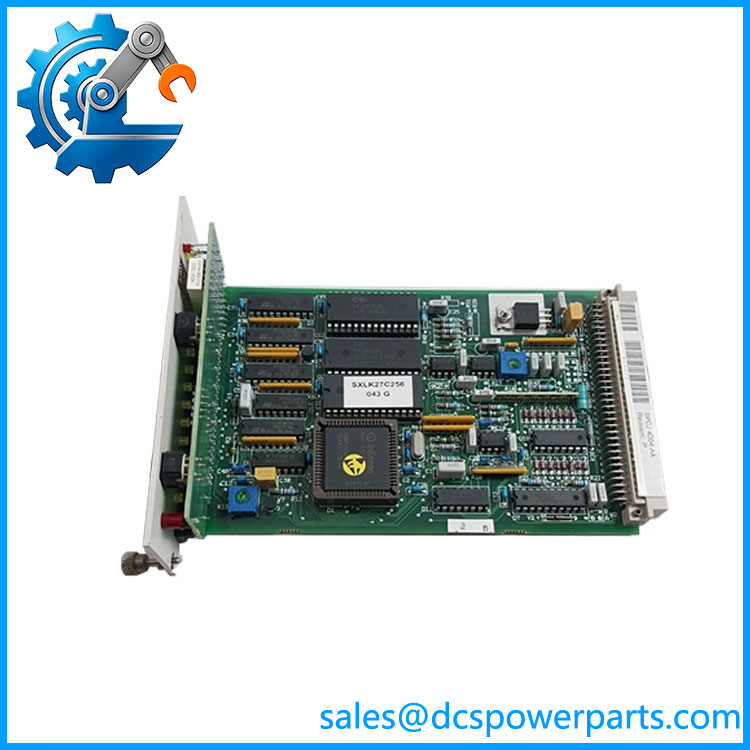
SPCJ4D34-AA
Major Features / Practical Advantages
Integrated Thermal Motor Protection
The thermal protection stage is more than a simple fixed overload threshold. The SPCJ 4D34 calculates motor thermal condition and provides adjustable full-load current, stall-time, cooling behavior, prior alarm, and restart-inhibit settings. The thermal current setting spans 0.50–1.50 × In, with 0.01 × In resolution. The cooling multiplier can be set from 1 to 64 times the heating time constant.
That matters on motors with repeated starts or substantial load variation. A replacement engineer should recover the existing thermal settings rather than simply entering the motor nameplate current and assuming the relay is correctly configured.
Two-Level Overcurrent Protection
The relay provides separate low-set and high-set overcurrent functions. The low-set stage covers 1.0–10.0 × In with operating times from 0.3 to 80 seconds. The high-set stage covers 0.5–20 × In with an operating-time range of 0.04–30 seconds.
The high-set stage is particularly important when checking an old motor protection scheme against the existing breaker or contactor clearing time. Do not copy settings from a different motor simply because the motors have similar ratings.
Earth-Fault Protection
The earth-fault stage provides a setting range of 1–100% In and an operating-time range of 0.05–30 seconds. The protection can be routed as a tripping or signaling function through the relay’s programmable output matrix.
Phase Unbalance and Phase-Sequence Protection
Phase-unbalance protection is adjustable from 10–40% of the phase current IL. ABB specifies approximately 1 second operation under a single-phasing condition and approximately 600 ms for incorrect phase sequence detection.
This makes the module useful on motors where loss of phase or incorrect rotation is a meaningful equipment risk, rather than treating the device as only an overcurrent relay.
Undercurrent and Loss-of-Load Detection
The undercurrent stage can be set from 30–80% of the motor full-load current setting, with an operating time from 2 to 600 seconds. It is intended for applications where loss of mechanical load can indicate a process or equipment fault, including pump and conveyor applications.
Startup and Stall Supervision
The startup supervision function allows current and time limits to be coordinated with motor acceleration. The startup current setting is 1.0–10.0 × In, while startup time is adjustable from 0.3–80 seconds. A cumulative startup-time counter can also inhibit further starts when configured limits are exceeded.
Legacy SPA Communication
The module supports ABB’s SPA fiber-optic serial bus architecture through a suitable SPA-ZC connection module. Documented data rates are 4800 or 9600 baud. This is legacy protection communications, not Ethernet-based IEC 61850 communication.
Related Products
- SPAM 150 C — Complete modular motor protection relay assembly containing the SPCJ 4D34 protection module.
- SPCJ 4D34 — Core motor protection relay module corresponding to the SPCJ4D34-AA identification.
- SPTU 240R2 — Auxiliary power/output relay module for 80–265 V AC/DC systems with normally open trip contact.
- SPTU 240R3 — 80–265 V AC/DC auxiliary power/output module with normally closed trip contact.
- SPTU 48R2 — 18–80 V DC power/output module with normally open trip contact.
- SPTU 48R3 — 18–80 V DC power/output module with normally closed trip contact.
- SPTE 4E3 — Input module used with the SPAM 150 C relay architecture.
- SPA-ZC 17 — SPA bus connection interface for the modular relay system.
- SPA-ZC 21 — Alternative SPA bus connection interface used for serial communication.
The complete SPAM 150 C system uses these modules in combination, so they should not be treated as interchangeable versions of the SPCJ 4D34 itself. ABB specifically documents the power-supply/output modules and input module as separate components.
FAQ
What is ABB used for?
It is a motor protection relay module for the ABB SPAM 150 C architecture. Its functions include thermal overload, phase overcurrent, earth fault, phase unbalance, phase-sequence protection, undercurrent, and motor startup/stall supervision.
Is a complete motor protection relay?
Not necessarily. SPCJ 4D34 is the protection module, while a complete SPAM 150 C installation also uses an input module and an auxiliary power/output relay module. The communications interface is another separate component.
Can I use a 1 A version in a 5 A CT circuit?
No. The relay installation must match the CT secondary configuration. ABB documents separate 1 A and 5 A input connections and different thermal/current withstand characteristics. Verify the original CT secondary rating before replacement.
Does support modern Ethernet or IEC 61850?
The documented communication interface is the ABB SPA fiber-optic serial bus, with selectable 4800 or 9600 baud data rates. It should therefore not be represented as a native Ethernet or IEC 61850 relay.
Can I hot-swap this module?
Do not assume hot replacement. This is a protection module installed inside a relay assembly connected to CT circuits, trip circuits, auxiliary power, and potentially fiber communications. Follow the site’s isolation procedure and the applicable ABB maintenance documentation before removing the module.
Does this support firmware v3.1?
The model number alone does not establish a firmware revision. This is a legacy microprocessor-based protection module, and firmware/version information should be verified from the physical unit, documentation, or the installed system rather than inferred from .
Will replacing the module preserve the motor protection settings?
Do not assume it will. The protection settings are part of the commissioned relay configuration. Before replacement, record or retrieve the existing thermal, overcurrent, earth-fault, unbalance, undercurrent, startup, and switchgroup settings. ABB documents front-panel setting/configuration functions and SPA-bus access.
What should I verify when purchasing a New Surplus ?
Verify the exact SPCJ 4D34 identification, board revision, current-input configuration, physical condition, connectors, and compatibility with the existing SPAM 150 C assembly. New Surplus status by itself does not prove that the module has never been installed or electrically tested.
Procurement Note
For a legacy replacement, the biggest procurement mistake is treating the protection module as an isolated commodity. The surrounding SPAM 150 C configuration matters.
Before ordering, compare the original relay’s SPCJ 4D34 module, CT secondary rating, SPTE 4E3 input module, SPTU power/output module, auxiliary voltage, trip-contact philosophy, SPA interface, and protection settings. ABB documents 80–265 V AC/DC and 18–80 V DC as separate auxiliary-supply arrangements through different SPTU modules; the AA suffix should therefore not be used by itself to infer the complete relay’s auxiliary voltage.
For a plant-critical motor, retain the original settings and protection coordination records before changing hardware. A physically compatible module with the wrong CT rating or missing configuration information can create a much bigger commissioning problem than simply having no spare.