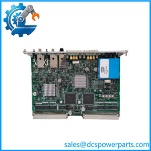
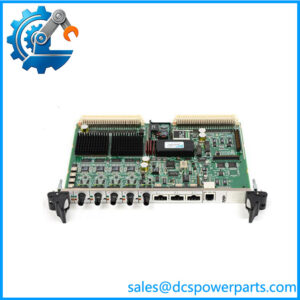
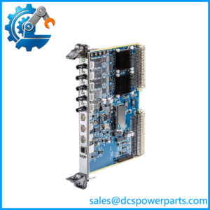
Description
Key Technical Specifications
| Parameter | Specification |
|---|---|
| Manufacturer | ZYGO Corporation |
| Product Model | ZMI-2001 |
| Product Family | ZMI 2000 Series |
| Product Type | Single-Axis Measurement Board |
| Measurement Axes | 1 |
| Board Format | 6U VME |
| VME Compliance | VMEBus Specification Revision C.1 |
| VME Addressing | A16 or A24 |
| Data Transfer | D16 or D32 |
| Interrupt Acknowledge | D08(0) |
| Power Requirement | +5 VDC ±5% at 3.5 A |
| Position Format | 36-bit, 2’s complement |
| Velocity Format | 32-bit, 2’s complement |
| Time Format | 32-bit, 2’s complement |
| Time Range | 107.4 seconds |
| Time Resolution | 25 ns |
| Optical Signals | Reference and measurement fiber-optic signals |
| Synchronization | Clock input or clock output |
| P2 Interface | High-speed measurement-data interface |
| Maximum P2 Data Rate | Up to 7.7 MHz |
| System Expansion | Up to 16 axes through the ZMI 2000 architecture |
The ZMI-2001 is specifically the single-axis member of the ZMI 2000 VME measurement-board family. The corresponding ZMI-2002 provides two axes on one 6U VME board.
The ZMI 2000 system’s published performance depends on the interferometer configuration. With a two-pass plane-mirror interferometer, the system specification gives λ/2048, approximately 0.31 nm, with a ±10.6 m position range and 2.1 m/s velocity limit. With a four-pass configuration, the resolution can reach approximately 0.15 nm, while a one-pass linear-interferometer configuration provides approximately 0.62 nm resolution and a 4.2 m/s velocity limit.
That distinction is important when writing a purchase specification: 0.31 nm should not be treated as an unconditional board-only accuracy figure. The actual result depends on the complete laser, interferometer, optical path, and measurement configuration.
Application Scenarios & Pain Points
A failed ZMI-2001 can stop a precision stage even though the VME controller and servo amplifier appear healthy. The frustrating part is that an optical-path problem can produce symptoms very similar to an electronics fault.
Typical Applications
- Precision Motion Stages: The single measurement axis can provide high-resolution displacement feedback for a linear or stage-positioning system.
- Semiconductor Equipment: ZYGO’s ZMI technology is used for precision stage measurement in semiconductor and photolithography equipment, where independent displacement feedback is required for accurate stage control.
- Legacy VME Motion Controllers: The 6U VME format makes the ZMI-2001 particularly useful when maintaining older VME-based metrology or motion-control equipment rather than redesigning the complete electronics cabinet.
- Multi-Axis Systems: Multiple ZMI-2001 boards can be combined through the P2 architecture. ZYGO’s documentation describes high-speed P2 data rates of up to 7.7 MHz and expansion to as many as 16 axes.
Field Case:
On an older precision stage, one axis may suddenly show position dropout while the VME system continues running. Before replacing the ZMI-2001, check the reference signal, measurement fiber, interferometer alignment, and connector condition. If the optical input is unstable, a replacement board may behave exactly like the original one.
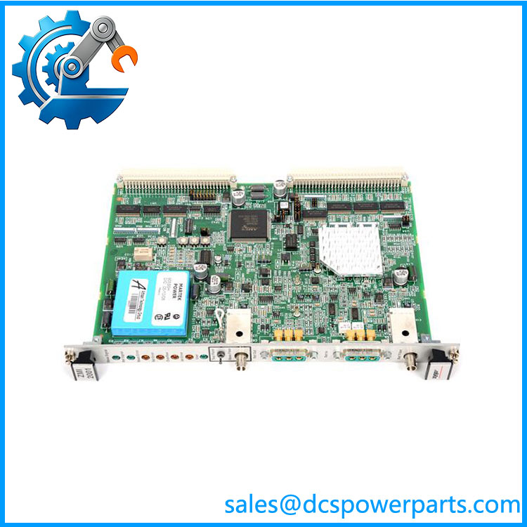
ZMI-2001
Related Products
- ZYGO ZMI-2002 — Dual-axis version of the same ZMI 2000 measurement-board architecture. It provides two interferometry axes on one 6U VME board, making it appropriate where two measurement channels are required.
- ZYGO ZMI-2400 — Later ZMI measurement-board family supporting one or two axes. It belongs to a different generation, so software, optical, timing, and VME compatibility must be checked before substitution.
- ZYGO ZMI-4004 — Four-axis VME/VME64x measurement board. Its higher channel density makes it attractive for system modernization, but it is not automatically electrically or software-compatible with a .
- ZYGO ZMI-4104C — Four-axis measurement electronics from the 4100 family. It offers a later hardware architecture and should be evaluated as a modernization option rather than assumed to be a drop-in replacement.
- ZYGO ZMI-501A — Stand-alone measurement-electronics system supporting two axes. Unlike the , it does not depend on the same 6U VME board format.
- ZYGO ZMI Go! — Modern compact ZMI electronics intended for contemporary motion-control integration. It is more suitable for a new control-system design than preservation of a legacy VME architecture.
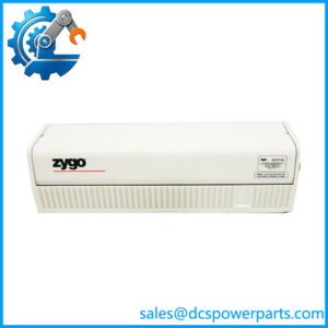
- ZYGO ZMI Linear Interferometer — Optical measurement component used for linear displacement measurement. It supplies the optical measurement path that the electronics process.
- ZYGO ZMI Plane Mirror Interferometer — Used for precision stage measurements where the optical geometry requires a plane-mirror arrangement. The ZMI 2000 specifications identify plane-mirror configurations as part of the system’s measurement-performance options.
The Engineer’s Guide: Field Pitfalls to Avoid
⚠️ Do Not Specify 0.15 nm or 0.31 nm Without Defining the Optical Configuration
The ZMI 2000 performance changes with the interferometer arrangement. The published figures are approximately 0.15 nm for four-pass PMI, 0.31 nm for two-pass PMI, and 0.62 nm for one-pass LI.
How to avoid it: When comparing a replacement, record the existing interferometer type and optical pass configuration before comparing resolution numbers.
⚠️ A VME Power-On Test Is Not a Measurement Test
The board can initialize correctly while the reference or measurement optical signal is missing.
How to avoid it: Require a functional test using known-good optical reference and measurement signals. Verify position data, velocity data, and error-status reporting—not just the LEDs.
⚠️ Check the P2 Interface Before Replacement
The P2 interface can carry high-speed measurement data to a servo card or motor controller. The wiring and synchronization arrangement are part of the machine’s architecture.
How to avoid it: Photograph the P2 connector and document clock input/output and downstream controller connections before removing the existing board.
Frequently Asked Questions (FAQ)
What is the ZYGO used for?
The is a single-axis 6U VME measurement board used in ZYGO displacement-measuring interferometer systems. It processes reference and measurement optical signals and provides position and velocity information for precision motion applications.
How many axes does support?
The board provides one measurement axis. If two axes are required on a single board, the related ZMI-2002 provides two. Multiple boards can also be combined in a larger ZMI system.
What is the resolution of the ?
The answer depends on the interferometer configuration:
- Four-pass PMI: approximately 0.15 nm
- Two-pass PMI: approximately 0.31 nm
- One-pass LI: approximately 0.62 nm
The corresponding published velocity limits are 1.05 m/s, 2.1 m/s, and 4.2 m/s, respectively.
These are system-performance figures, not a guarantee that an installed machine will achieve the same result under every environmental condition.
What are the power requirements?
The ZMI 2000 specification gives +5 VDC ±5% at 3.5 A for the .
When installing a replacement, check the actual VME backplane voltage under load. A marginal power supply can create intermittent behavior that is easily mistaken for a defective measurement board.
Is a VME board?
Yes. It is a 6U VME measurement board supporting A16/A24 addressing and D16/D32 data transfer under VMEbus specification revision C.1.
The board also has a P2 interface intended for high-speed measurement-data distribution.
Can ZMI-2002 replace ?
Not as an exact functional equivalent. The ZMI-2002 provides two axes, whereas the provides one.
If the control system is configured for a single channel, installing a two-axis board may require configuration changes. Confirm the host software, axis mapping, P2 wiring, and system synchronization before substitution.
What should I request when purchasing a refurbished ?
Request:
- Actual front and rear photographs
- Complete model and part-number markings
- Serial number and PCB revision
- VME P1/P2 connector inspection
- +5 VDC load test
- VME initialization test
- Reference optical-input test
- Measurement optical-input test
- Position-data verification
- Velocity-data verification
- Clock synchronization test
- Error-status verification
- P2 data-output test where applicable
- Test report
- Warranty terms
For this type of metrology board, “tested and powers on” is not enough. The meaningful acceptance test is a known-good ZMI optical setup producing stable displacement data through the board’s intended VME/P2 interface. The ZMI 2000 documentation specifically identifies reference and measurement fiber signals, synchronization, and measurement-status monitoring as integral parts of the board architecture.