Description
Key Technical Specifications
| Parameter | Specification |
|---|---|
| Product model | 9440/15-01-11 |
| Manufacturer | R. STAHL |
| Product family | IS1 Remote I/O |
| Product type | CPU and power module (CPM2) |
| Installation classification | Zone 2 / Division 2 |
| Standard fieldbus | PROFIBUS DP V0 |
| Fieldbus interface | RS-485 |
| Redundant fieldbus connection | Supported through secondary interface |
| Auxiliary supply | 24 VDC |
| Permitted supply range | 20–35 VDC |
| Current consumption, no I/O modules | 0.3 A at 24 VDC |
| Current consumption, 8 I/O modules | Approx. 2.5 A at 24 VDC |
| Current consumption, 16 I/O modules | Approx. 4.9 A at 24 VDC |
| Supported I/O modules | Up to 16 |
| Display | 2-line, 16-character LCD |
| Service interface | RS-485 ServiceBus |
| Galvanic isolation | 1,500 VAC for specified interface and supply separations |
| Weight | Approx. 0.56 kg |
These values are supported by R. STAHL’s product documentation.
Product Introduction
The R. STAHL 9440/15-01-11 functions as the central processing and power-supply unit in an IS1 remote I/O field station. It acts as a gateway between the station’s internal BusRail and the higher-level automation system. The module also supplies the connected I/O modules and their field circuits through the BusRail.
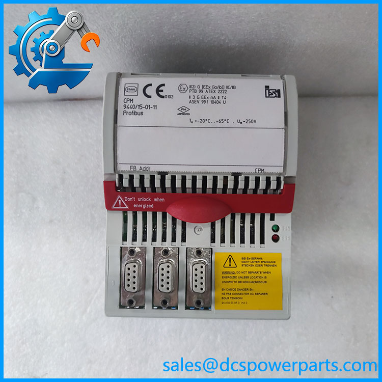
944015-01-11
Its standard communication version uses PROFIBUS DP V0 over RS-485. The station can accommodate up to 16 compatible I/O modules, subject to the system configuration and power budget. A local LCD displays the bus address, operating condition, module information, diagnostics, and signal values. The ServiceBus supports commissioning and diagnostic operations.
Major Features and Advantages
Remote I/O station processing
The module handles data exchange between the IS1 internal I/O bus and the plant-level PROFIBUS network. It provides the communication gateway required for the remote station to operate as part of a distributed control architecture.
Integrated power distribution
The internal power supply supports the CPU, connected I/O modules, and field circuits. Undervoltage monitoring and polarity-reversal protection help identify or prevent certain supply-related faults.
PROFIBUS DP communication
The standard -01-11 version uses PROFIBUS DP V0. Copper RS-485 transmission distance depends on baud rate, reaching up to 1,200 m at lower rates. A fiber-optic option can support longer distances with compatible hardware.
Redundancy support
The IS1 architecture supports redundant CPU and fieldbus configurations. The primary and redundant modules occupy designated BusRail positions, and the redundant power arrangement uses internal diode decoupling. Actual redundancy behavior depends on the system hardware, firmware, and configuration.
Local diagnostics
The two-line LCD and status indicators provide local access to bus status, module conditions, error information, and process values. This is useful during commissioning and fault isolation.
Application Scenarios and Field Pitfalls
Typical applications include:
- Distributed process control systems.
- Oil and gas instrumentation.
- Chemical and petrochemical plants.
- Hazardous-area remote I/O installations.
- Industrial process monitoring and control.
- PROFIBUS-based instrumentation networks.
Important engineering checks:
- Hazardous-area classification: The 9440/15-01-11 is the Zone 2 / Division 2 version. Do not substitute it for the Zone 1 version 9440/12-01-11.
- Bus protocol: Confirm PROFIBUS DP V0 requirements. Do not assume the standard model includes the DP V1 HART functionality of the C1243 variant.
- Power budget: Calculate the total consumption of all installed I/O modules before connecting the station.
- Redundancy: Check whether the original installation uses one or two CPU and power modules.
- BusRail position: The primary module belongs in the first designated slot; the redundant module occupies the second.
- Firmware compatibility: Check controller firmware and I/O module firmware before replacing the CPU module.
- Enclosure requirements: Follow the applicable hazardous-area installation instructions, including enclosure and wiring-separation requirements.
Related Products and Variants
| Model | Communication | Distinction |
|---|---|---|
| 9440/15-01-11 | PROFIBUS DP V0 | Standard Zone 2 CPU and power module |
| 9440/15-01-11-C1243 | PROFIBUS DP V1 | HART-capable variant |
| 9440/15-01-11-C1198 | Modbus RTU | Modbus communication variant |
| 9440/12-01-11 | PROFIBUS / Modbus family | Zone 1 CPU and power module |
The suffix is important: these are different communication or installation configurations, not interchangeable ordering codes.
Procurement and Quality Control
For replacement procurement, request:
- Full nameplate and article-number photographs.
- Hardware and firmware revision.
- PROFIBUS address and configuration records.
- Confirmation of the installed I/O module count.
- Power-supply and BusRail condition.
- Functional test of the LCD, status indicators, and fieldbus interface.
- Verification of redundant CPU operation if used in the original installation.
Procurement recommendation: Specify R. STAHL 9440/15-01-11, IS1 Zone 2 PROFIBUS DP V0 CPU and Power Module. Confirm the hardware revision and firmware against the existing field station before installation.
A particularly important distinction is that 9440/15-01-11 is the standard DP V0 version. If your existing installation requires DP V1 with HART, verify the C1243 suffix before ordering.