Description
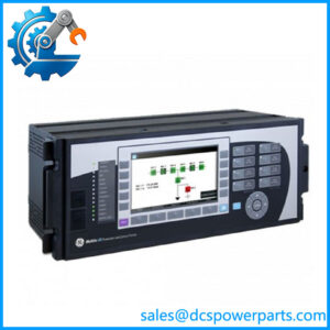
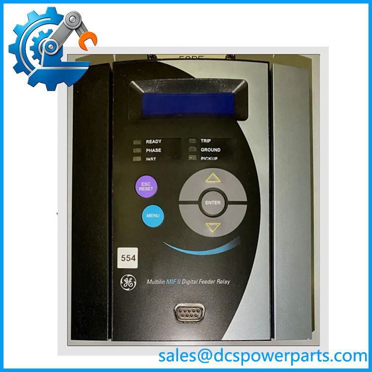
GE Multilin MIFIIPI55E20HI00 MIF II Digital Feeder Relay
Key Technical Specifications
| Parameter | Specification |
|---|---|
| Product Model | MIFIIPI55E20HI00 |
| Manufacturer | GE Multilin |
| Product Family | MIF II |
| Product Type | Digital feeder protection relay |
| Primary Application | Feeder protection and monitoring |
| Current Configuration | 55-series configuration; verify exact CT input rating |
| Protection Functions | Overcurrent / feeder protection functions; exact functions depend on configuration |
| Measurement | Three-phase/current-system measurements as configured |
| Control | Programmable relay logic and output control, configuration-dependent |
| Communication | Verify exact installed interface and protocol |
| Auxiliary Supply | Verify against relay nameplate |
| Mounting | Panel-mounted relay |
| Front Interface | Local relay display/keypad arrangement |
| Environmental Rating | Verify exact MIF II hardware revision |
| System Integration | Protection, metering, control, and SCADA applications |
Ordering-Code Caution
The string MIFIIPI55E20HI00 contains several configuration fields, so it should not be interpreted simply as a model number followed by a generic current rating. The exact E20HI00 option combination needs to be preserved when ordering a replacement. Current public listings confirm the complete code but do not provide a sufficiently reliable OEM ordering-code breakdown for every character.
Product Introduction
The GE Multilin MIFIIPI55E20HI00 is a MIF II digital feeder protection relay designed for electrical distribution protection and monitoring. Unlike a conventional electromechanical overcurrent relay, the MIF II platform combines protection functions with digital measurement, event information, programmable logic, and system interfacing. The exact protection and communications package depends on the relay configuration.
For maintenance teams, the important point is that this is a protection IED, not a general-purpose PLC input module. Replacement work must preserve the CT/VT arrangement, pickup and time-current settings, trip logic, breaker interface, auxiliary supply, communications configuration, and stored protection parameters. A physically compatible relay without the correct configuration can produce a substantially different protection scheme.
MIFIIPI55E20HI00
Application Scenarios & Field Pitfalls — The Engineer’s Perspective
Engineering Pain Point
With legacy feeder relays, the difficult part is often not installing the replacement hardware. The risk is restoring the original protection behavior. CT ratios, phase sequence, residual-current wiring, breaker trip circuits, relay curves, time delays, output logic, and communications settings all affect how the feeder operates during a fault. A replacement should therefore be treated as a protection-system restoration project rather than a simple hardware swap.
Typical Applications
- Medium-voltage feeder protection — monitoring and tripping for feeder faults.
- Industrial distribution systems — protection of motors, transformers, switchgear feeders, and plant distribution circuits where the MIF II configuration is suitable.
- Utility distribution equipment — feeder protection and measurement applications.
- Legacy GE Multilin protection panels — replacement of installed MIF II relays while retaining the existing switchgear architecture.
Technical Pitfalls to Avoid
- Do not assume every MIF II has the same protection package.
The ordering code determines the hardware and options. Compare the completeMIFIIPI55E20HI00code with the existing relay. - Verify CT ratios and polarity.
Incorrect CT ratio, phase assignment, or polarity can cause incorrect current measurement and unwanted protection operation. - Preserve the original trip logic.
Record output assignments, breaker-trip circuits, interlocks, auxiliary relays, and any seal-in logic before removing the old relay. - Do not copy specifications from MIFIIPI55E10HI00 without verification.
Public listings describe the E10HI00 variant in detail, but the user’s E20HI00 is a different ordering configuration. - Back up relay settings before replacement.
Protection curves, pickup values, delays, logic equations, communications parameters, and event settings should be documented before commissioning. - Verify communications separately.
Do not assume that a replacement relay has the same communications interface, address, baud rate, protocol, or station configuration as the installed unit. - Perform secondary-injection testing.
Confirm measurement scaling, pickup thresholds, timing, output contacts, and trip logic before returning a protected feeder to normal service.
Related Products
- GE Multilin MIF II — the product family containing the MIFIIPI55E20HI00; exact protection and hardware options vary by ordering code.
- GE MIFIIPI55E10HI00 — closely related MIF II 55-series configuration; useful for family comparison but not automatically interchangeable.
- GE MIFIINI05E20HI00 — another MIF II configuration appearing in equipment records; different ordering code and therefore requiring configuration verification.
- GE MIVII1000E00HI00 — another GE Multilin digital protection relay appearing alongside MIF II equipment; different relay family and application.
- GE Multilin 369 — separate GE Multilin motor-management/protection family; not a direct MIF II feeder-relay replacement.
- GE Multilin 750/760 — separate feeder protection platform; application and hardware architecture must be checked before considering migration.
Procurement and Replacement Note
For procurement, use the complete identification:
GE Multilin — MIF II Digital Feeder Protection Relay.
Do not shorten the order code to MIF II 55. The E20HI00 portion is part of the hardware/configuration identification and should remain intact on the purchase specification. Public records confirm the exact model as a MIF II digital feeder relay, but they do not provide enough reliable OEM documentation to assign every ordering-code character or every electrical rating with confidence.
Before approving a replacement, compare the original relay’s complete ordering code, CT/VT configuration, auxiliary supply, firmware, protection settings, output assignments, communication interface, and panel cutout. If the original relay is still accessible, export or document its settings before removal.
One important quality-control point: some online descriptions incorrectly mix MIF II protection-relay specifications with unrelated descriptions of industrial process input modules. The exact is documented as a Multilin MIF II relay, so it should be specified and tested as protection equipment, not as a Mark VIe analog input module.