Description
Product Introduction
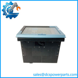
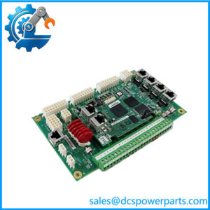
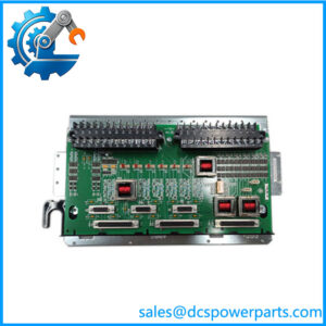
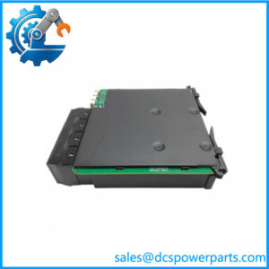
A wind turbine converter can experience multiple control faults when an auxiliary power rail drops out, even if the main DC link remains energized. The GE IS210AEPSG1BCA is an AEPS power supply printed circuit board associated with GE Energy wind-converter control hardware. Its role is to provide operating power to designated control and interface circuits.
In documented AEPSG1B configurations, the board generates several output rails for controller electronics and associated interface boards. The exact output arrangement and jumper settings depend on the converter cabinet configuration. Before ordering the GE IS210AEPSG1BCA, verify the board markings, installed location, output requirements, and compatibility with the existing assembly.
Key Technical Specifications
| Parameter | Specification |
|---|---|
| Product model | IS210AEPSG1BCA |
| Manufacturer | GE Energy / General Electric |
| Functional acronym | AEPS |
| Product type | Alternative Energy Power Supply PCB |
| Application | Wind turbine converter control system |
| Associated system | Documented 2.x MW permanent-magnet-generator (PMG) converter configurations |
| Input source | DC link; exact operating range must be verified from the converter documentation |
| P24A output | +24 VDC, 1.5 A in the documented G1B configuration |
| IP24 output | Isolated 24 VDC, 0.5 A in the documented G1B configuration |
| P24C output | +24 VDC, 2 A in the documented G1B configuration |
| N24C output | −24 VDC, 2 A in the documented G1B configuration |
| IP5A / IP5B outputs | Isolated 5 VDC, 0.5 A each in the documented G1B configuration |
| AC1 / AC2 outputs | 25 kHz square-wave power for designated interface boards in the documented G1B configuration |
| Protection | Multiple fused output circuits in the documented G1B design |
| Status indication | Output-status LEDs reported for the G1B board family |
| Configuration | JP1 cabinet-mode selection is documented for the G1B family |
| Mounting | Internal converter-cabinet PCB mounting |
| Communication protocol | No independent fieldbus interface established; this is a power supply board |
| Operating temperature | Confirm using the applicable GE equipment documentation |
| Lifecycle | Legacy hardware; verify actual stock and condition |
Important specification qualification: The detailed electrical data above comes from documentation describing the IS210AEPSG1B board family, while the requested part is IS210AEPSG1BCA. Do not assume every rating or jumper configuration applies unchanged to the exact suffix. The GE parts listing identifies IS210AEPSG1BCA as an AEPS board, but the precise suffix-specific electrical drawing should be checked before installation.
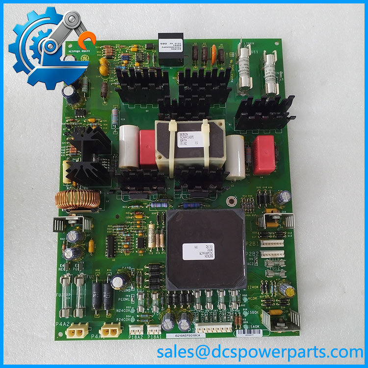
IS210AEPSG1BCA
Application Scenarios and Pain Points
When several converter-control boards lose power simultaneously, the root cause may be a failed auxiliary supply rail rather than multiple independent controller failures. The AEPS board is relevant to troubleshooting power distribution in compatible GE wind-converter installations.
- Converter Master Cabinet maintenance: Supplies operating power to designated converter control electronics.
- Converter interface-board power: Provides positive and negative 24 VDC rails and isolated low-voltage outputs in the documented G1B configuration.
- Converter diagnostics: Output LEDs and test points can help technicians identify missing power rails on the applicable board revision.
- Legacy wind turbine repairs: Supports maintenance of existing installations where the original AEPS hardware and wiring configuration are retained.
Field note: If an output LED is off, do not replace the fuse immediately without investigating the cause. Check the relevant load, wiring, and supply condition under the approved maintenance procedure. A blown fuse may be a symptom of a downstream short or an overloaded circuit.
Related Products
These are related GE wind-converter components or AEPS variants, not confirmed direct replacements for IS210AEPSG1BCA.
- IS210AEPSG1B — Related AEPS power supply board designation; verify suffix and revision differences.
- IS200AEPSG1AAA — Earlier AEPS-family board listed in GE Energy spare-part references.
- IS210AEPSG1ABB — Related AEPS variant; electrical and installation compatibility require verification.
- IS210AEPSG1ACC — Related AEPS variant with a different suffix.
- IS210AEPSG1BBA — Related G1B-series ordering variant.
- IS210AEPSG1BCB — Another listed G1B-series AEPS variant.
- IS200AEPCH1A — Alternative Energy Pitch Controller board, a separate control function.
- IS200AEPAH1AAA — Alternative Energy Pitch Assembly board, used for a different subsystem function.
Engineer’s Guide: Replacement Checks
1. Match the full part number.
Warning: Do not order solely by the IS210AEPSG1B prefix. Confirm the complete designation, revision markings, connector layout, and physical dimensions.
2. Confirm the installation location and jumper configuration.
The documented AEPSG1B family uses JP1 to select a cabinet operating mode. Verify the correct setting for the actual installation; do not copy settings from a different cabinet without checking the system drawing.
3. Check every output rail and downstream load.
Confirm the specified positive and negative 24 VDC outputs, isolated 5 VDC supplies, and any designated AC outputs against the exact board documentation. Inspect the related loads and fuses before energizing a replacement.
For used or refurbished stock, request photographs of the board front and back, full part and revision labels, confirmation of the tested output rails, repair history if applicable, and written warranty terms.
Frequently Asked Questions
Q1. What is the GE used for?
It is an AEPS power supply board associated with GE Energy wind-converter control systems. Its purpose is to provide power to designated control and interface circuits.
Q2. Is the a standard 24 VDC power supply?
It should not be treated as a generic 24 VDC supply. The documented AEPSG1B design generates multiple outputs, including positive and negative 24 VDC, isolated 5 VDC, and designated 25 kHz outputs. Confirm the exact configuration for the requested suffix.
Q3. Can I replace it with IS210AEPSG1B or IS210AEPSG1BCB?
Not without checking compatibility. Similar AEPS designations may have different assembly details or ordering revisions. Confirm the original equipment bill of materials, connector layout, and output requirements before substitution.
Q4. What does the JP1 jumper do?
Documentation for the related G1B board family describes JP1 as a cabinet-mode selector. The correct position depends on the installation location and converter configuration. Verify the exact board documentation before changing it.
Q5. How can I diagnose a missing output voltage?
Use the applicable wiring diagram and board test-point references to measure the affected rail safely. Inspect the associated fuse, input supply, connectors, and downstream load. Follow the plant’s electrical isolation and testing procedures.
Q6. Is the discontinued?
A parts listing identifies this model as discontinued by the manufacturer. Availability may therefore depend on remaining spare stock, surplus inventory, or refurbished units. Confirm the condition of the specific unit offered.
Q7. What should I confirm before purchasing?
Check the complete model number, board revision, required cabinet configuration, included hardware, output-test evidence, warranty coverage, and dispatch lead time. For a critical converter, also confirm that the replacement matches the approved electrical configuration before scheduling installation.