Description
Product Introduction
When a turbine control system develops inconsistent contact indications or relay-output faults, the terminal board, field wiring, and connected I/O pack all need to be checked before replacing components. The GE IS200TDBTH6ACD is a Mark VIe TDBT discrete I/O terminal board designed to interface field contact circuits with compatible control-system I/O hardware.
Its 24 contact inputs and 12 Form-C relay outputs support discrete signal handling in turbine control applications. For replacement planning, confirm the input wetting voltage, relay circuit arrangement, PDIO connections, and exact board revision against the installed system drawings.
Key Technical Specifications
| Parameter | Specification |
|---|---|
| Model | IS200TDBTH6ACD |
| Manufacturer | General Electric |
| Series | Mark VIe |
| Functional acronym | TDBT |
| Product type | Discrete I/O terminal board |
| Contact inputs | 24 group-isolated channels |
| Relay outputs | 12 Form-C relay channels |
| Nominal input wetting voltage | 24, 48, or 125 VDC, depending on circuit configuration |
| Reported wetting-voltage ranges | 16–32 VDC, 32–64 VDC, and 100–145 VDC |
| Input current | 2.5 mA for channels 1–21; 10 mA for channels 22–24, as reported in product documentation |
| Input filtering | Hardware filtering and noise-suppression circuitry |
| I/O pack interface | Three PDIO connection positions for applicable redundant configurations |
| Power requirements | Depends on the associated I/O pack and circuit configuration; verify system documentation |
| Mounting | DIN rail or flat mounting |
| Configuration | Base terminal board is reported to have no hardware jumpers |
| Operating temperature | −30°C to +65°C reported; confirm the applicable manual |
| Lifecycle status | Confirm current availability and approved replacement status |
These values are drawn from product listings and technical descriptions. Relay contact ratings and the precise electrical limits should be confirmed from the applicable GE hardware manual before wiring or commissioning.
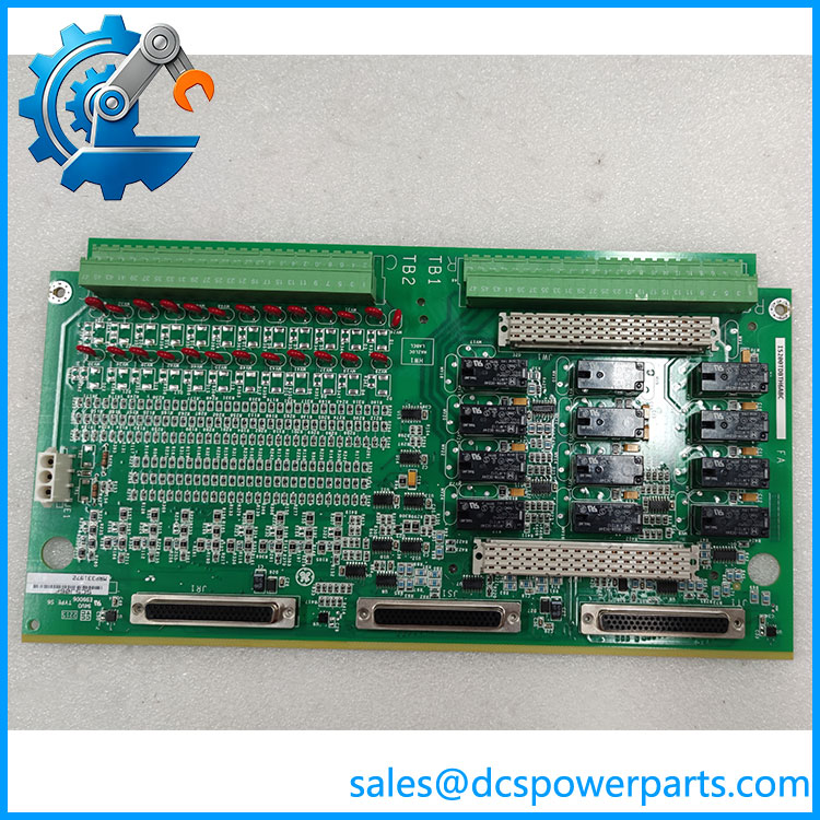
IS200TDBTH6ACD
Application Scenarios and Pain Points
In turbine control cabinets, a terminal-board fault can appear as a failed field contact, an unreliable status indication, or a relay output that does not behave as expected.
- Turbine control systems: Interface field contacts with compatible Mark VIe control hardware.
- Discrete status monitoring: Collect signals from switches, interlocks, and other contact-based field devices.
- Relay control circuits: Provide Form-C relay outputs for control functions supported by the configured system.
- Redundant control installations: Support compatible PDIO connections in the system’s specified redundant architecture.
Field note: Do not diagnose a discrete I/O fault from the terminal board alone. Check field-device voltage, terminal wiring, the connected I/O pack, network communication, and controller diagnostics before replacing hardware.
Related Products
The following models are useful for comparison when maintaining Mark VIe discrete I/O systems. They are not automatically interchangeable.
| Model | Relationship |
|---|---|
| IS200TDBTH6A | Related TDBT terminal-board designation; confirm revision and approved substitution details. |
| IS200TDBTH6ABC | Related Group 6 TDBT variant; compare the complete part number and assembly revision. |
| IS200TDBTH4A | TDBT variant with a different group designation. |
| IS200TDBTH2A | Another TDBT family variant; confirm its channel and system configuration. |
| IS200WROBH1A | Optional relay-output board used with compatible TDBT configurations to provide additional relay-circuit functionality. |
| IS200TRLYH1B | Relay terminal board with a different assembly design; do not assume functional equivalence without the system drawings. |
GE-related product documentation identifies these parts within the TDBT and associated relay-terminal-board family. Verify the exact assembly, I/O pack, and redundancy configuration before selecting a substitute.
Engineer’s Guide: Three Checks Before Replacement
- Verify the complete assembly number. Record the full
IS200TDBTH6ACDdesignation, revision markings, and any associated option-board number. Compare these with the installed bill of materials and wiring drawings. - Confirm the field input and relay circuits. Identify the nominal wetting voltage for each contact-input group and confirm the required relay contact arrangement. Never infer a relay’s permissible load from the Form-C designation alone.
- Check the I/O pack and redundancy topology. Verify the PDIO pack type, connector assignment, controller network connections, and system configuration. In redundant installations, an incorrect connection or incompatible assembly may prevent the intended architecture from operating correctly.
Before removing or installing the board, follow site lockout/tagout and electrical isolation procedures. Label field wiring and validate input states, relay operation, and controller diagnostics during controlled commissioning.
Frequently Asked Questions
Q1. What is the GE IS200TDBTH6ACD?
It is a GE Mark VIe TDBT discrete I/O terminal board with 24 contact inputs and 12 Form-C relay outputs.
Q2. Does it support 24 VDC inputs?
The board is documented for externally supplied contact-input wetting voltages of 24, 48, or 125 VDC nominal. The actual circuit range must match the installation’s configuration.
Q3. Is IS200TDBTH6ACD compatible with Mark VIe PDIO packs?
It is documented for use with compatible PDIO I/O packs. Confirm the exact pack type, connector assignment, and controller topology before installation.
Q4. Can IS200TDBTH6A replace IS200TDBTH6ACD?
A related or superseding designation is reported in product listings, but that does not by itself establish interchangeability. Confirm the approved cross-reference and revision compatibility for the specific system.
Q5. Does the base board require hardware jumper settings?
Product documentation reports no hardware jumpers on the base TDBT board. An optional relay board may have its own jumper configuration, which must be checked separately.
Q6. What should I request when purchasing a refurbished board?
Request clear photographs of the label and connectors, revision details, inspection records, functional test results, and written warranty terms. Confirm whether testing included the relevant input and relay-output functions.
Q7. What information is needed to verify compatibility?
Provide the installed board’s full part number, the connected PDIO pack model, the controller redundancy arrangement, and the relevant wiring diagram. This helps determine whether the replacement matches the existing I/O design.
Procurement recommendation: Treat as a configuration-dependent terminal board, not a generic discrete I/O replacement. Exact revision identification, field voltage, relay wiring, and PDIO compatibility are the key checks before purchase.